Download
1 / 18
180 likes | 276 Views
Acceleration Overview. J. Scott Berg Brookhaven National Laboratory January 8, 2014. Acceleration Goals. Accelerate rapidly to avoid decays High average RF gradient: ≈5 MV/m for 70% transmission Control costs and power use Make many passes through RF

E N D
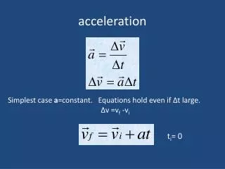
Acceleration Overview J. Scott Berg Brookhaven National Laboratory January 8, 2014
Acceleration Goals • Accelerate rapidly to avoid decays • High average RF gradient: ≈5 MV/m for 70% transmission • Control costs and power use • Make many passes through RF • To simultaneously maintain high average RF gradient: high average dipole field • Handle large emittance beams
Beam Properties • Wide variety of emittances to accelerate • Biggest challenge is the large longitudinal emittance for the higher energy colliders • Higgs factory beam is more reasonable size • But still need to accelerate large longitudinal emittance through that energy range • Neutrino factory beam has very large transverse emittance • Specific solution for neutrino factory discussed earlier
Accelerator Types: Linac • Best for low energies, large beams • Large longitudinal emittance • 325 MHz SCRF not possible for low energies (until about 700 MeV) • Use technologies from final cooling for acceleration (expensive) • Induction linacs: low gradient • Low frequency RF: low gradient • Cooling RF: high gradient, longitudinal acceptance • No re-use of RF
Accelerator Types: RLA • Recirculating linear accelerator • Multiple passes through RF • Large longitudinal acceptances possible • Can’t put too many beamlines in switchyard • Large emittance beam • Limits number of passes • Dogbone geometry • Maximizes separation for given number of passes • Gives very high average accelerating gradient • Start these right after cooling RF
Accelerator Types: FFAG • Fixed field alternating gradient accelerator • Single beamline with wide energy range • No switchyard limiting number of passes • Trade single beamline with large magnets for many beamlines with smaller magnets in RLA • Passes limited by tolerable longitudinal emittance distortion • Worse with large longitudinal emittance • Do not appear to be cost-effective with 70 mm longitudinal emittance
Accelerator Types: Synchrotron • Synchrotron with very fast ramping time • 1.5 T maximum fields • Low average bend field: low RF efficiency • Pulse times: 63–375 GeV, 200 µs for 5 MV/m • Beam moves in aperture to correct time of flight • Pulse times too short at low energies • Hybrid synchrotron • Alternate fixed-field high-field dipoles and low-field bipolar pulsed dipoles to get large average dipole field • More passes through RF, but faster ramp times • Ideal solution at high energies
Acceleration Scenario • Linac with cooling technologies to ≈700 MeV • RLA to 63 GeV • Compatible with 70 mm longitudinal emittance • Acceleration to ≈375 GeV • RLA or non-hybrid synchrotron • Appear to have comparable costs • Synchrotron could share tunnel with next stage • Relatively safe technologies • Hybrid synchrotron (two stages) • Appears better for cost/efficiency • Short pulse times a challenge (70 µs for 5 MV/m)
Acceleration Scenario • Hybrid synchrotron above ≈375 GeV • Gets easier as energies increase • 10 T SC dipoles, 1.5 T ramped dipoles, looks like could accelerate to 3 TeV on Fermilab site
Design Challenges RLA switchyard layout Injection/extraction Time of flight correction Collective effects Showstoppers unlikely, but cost escalation an issue
Status • NuMAX concept in place • Concept for 63 GeV acceleration in place • May need modifications for 70 mm longitudinal emittance • Hybrid synchrotron design exists • Needs modification for current magnet parameters • Needs time of flight correction • Should look at chromaticity correction • Needs to be scaled to other energies
Key Technologies • RF • High-gradient SCRF: higher helps efficiency & decays • High gradients for cooling RF systems used for early acceleration • Superconducting magnets: higher fields help efficiency and decays • Kickers for injection/extraction
Key Technologies: Pulsed Magnets • Workable designs for 1.5 T • 1.8 T with grain oriented steel, but • Field line pinning makes this sensitive to construction tolerances • Not possible to model accurately with existing codes • FeCo could achieve 2.2 T • But need shielding solution for Co activation, unlikely • Quadrupole design • Better understand steel behavior with short pulse times, high fields, thin laminates • Pushing limits on existing measurements • Consequences of short pulse times • Power supplies: controlled ramp