Download
1 / 17
170 likes | 241 Views
Epitaxial Silicon Detectors for Particle Tracking Overview on Radiation Tolerance at Extreme Hadron Fluence. G. Lindström (a) , E. Fretwurst (a) , F. Hönniger (a) , G. Kramberger (b) , M. Moll (c) , E. Nossarzewska (d) , I. Pintilie (e) , R. Röder (e)

E N D
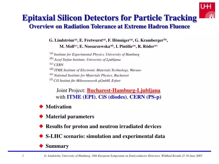
Epitaxial Silicon Detectors for Particle Tracking Overview on Radiation Tolerance at Extreme Hadron Fluence G. Lindström(a), E. Fretwurst(a), F. Hönniger(a), G. Kramberger(b), M. Moll(c), E. Nossarzewska(d), I. Pintilie(e), R. Röder(e) (a) Institute for Experimental Physics, University of Hamburg (b) Jozef Stefan Institute, University of Ljubljana (c) CERN (d) ITME Institute of Electronic Materials Technology, Warsaw (e) National Institute for Materials Physics, Bucharest (f) CiS Institut für Mikrosensorik gGmbH, Erfurt Joint Project: Bucharest-Hamburg-Ljubljanawith ITME (EPI), CiS (diodes), CERN (PS-p) • Motivation • Material parameters • Results for proton and neutron irradiated devices • S-LHC scenario: simulation and experimental data • Summary 1 G. Lindström, University of Hamburg, 10th European Symposium on Semiconductor Detectors, Wildbad Kreuth,12-16 June 2005
Motivation • LHC upgrade to Super-LHCLuminostity LHC: L~ 1034 cm-2s-1 S-LHC: L~ 1035 cm-2s-1Expected radiation at inner pixel layer (4 cm) under S-LHC conditions:Fluence for fast hadrons: 1.61016 cm-2Dose: 420 Mrad • Proposed Solution: thin EPI-SI for small size pixels Si best candidate: low cost, large availability, proven technology thickness doesn’t matter! CCE limited at 1016 cm-2by e 20 m,h 10 m small pixel size needed, allows thin devices with acceptable capacitance for S/Nhigh Neff,0 (low ρ) provides large donor reservoir, delays type inversion • Needed data for prediction of S-LHC operational scenario: • Reliable projection of damage data to S-LHC operation • Full annealing cycles at elevated temperatures • Charge collection efficiency at very high fluences 2 G. Lindström, University of Hamburg, 10th European Symposium on Semiconductor Detectors, Wildbad Kreuth,12-16 June 2005
Material Parameters • Oxygen depth profilesSIMS-measurements after diode processing O diffusion from substrate into epi-layerinterstial Oi + dimers O2i [O] 25 µm > [O] 50 µm process simulation yields reliable [O] • Resistivity profilesSR before diode process, C-V on diodes SR coincides well with C-V method Excellent homogeneity in epi-layers (SIMS-measurements: A. Barcz/ITME, Simulations: L. Long/CiS) (SR-measurements: E. Nossarzewska, ITME) 3 G. Lindström, University of Hamburg, 10th European Symposium on Semiconductor Detectors, Wildbad Kreuth,12-16 June 2005
Typical Annealing Curves Typical annealing behavior of EPI-devices: Vfd development:Inversion only(!) during annealing ()(100 min @ 80C ≈ 500 days @ RT) EPI never inverted at RT (t < 500d), even for 1016 Comparison EPI- with FZ-device: Vfd development:short term: EPI increasing, FZ decreasing long term: EPI decreasing, FZ increasing EPI not inverted, FZ inverted, alreadyimmediately after irradiation 4 G. Lindström, University of Hamburg, 10th European Symposium on Semiconductor Detectors, Wildbad Kreuth,12-16 June 2005
Parameterization of Annealing Results Change of effective “doping“ concentration: Neff = Neff,0 – Neff (,t(T)) Standard parameterization: Neff = NA(,t(T)) + NC() + NY(,t(T)) Annealing components: • Short term annealing NA(,t(T)) • Stable damage NC()NC = NC0(1-exp(-cΦeq) + gCΦeqgC negative for EPI (effective positive space charge generation!) • Long term (reverse) annealing:Two components: NY,1(,t(T)), first order process NY,2(,t(T)), second order processNY1, NY2~ Φeq, NY1+NY2 similar to FZ 5 G. Lindström, University of Hamburg, 10th European Symposium on Semiconductor Detectors, Wildbad Kreuth,12-16 June 2005
Stable Damage Component Neff(t0): Value taken at annealing time t0 at which Vfd maximum • No space charge sign inversion after proton and neutron irradiationIntroduction of shallow donors overcompensates creation of acceptors • Protons: Stronger increase for 25 µm compared to 50 µm higher [O] and possibly [O2] in 25 µm (see SIMS profiles) • Neutrons: Similar effect but not nearly as pronounced most probably due to less generation of shallow donors and as strong influence of acceptors 6 G. Lindström, University of Hamburg, 10th European Symposium on Semiconductor Detectors, Wildbad Kreuth,12-16 June 2005
Shallow Donors, the real issue for EPI -Comparison of 25, 50 and 75 µm Diodes- SIMS profiling of [O] Stable Damage after PS p-irradiation Generation of positive space charge most pronounced in 25 µm diodes Defect spectroscopy after PS p-irradiation Generation of recently found shallow donors BD (Ec-0.23 eV) strongly related to [O] Possibly caused by O-dimers, outdiffused from Cz with larger diffusion constant dimers monitored by IO2 complex SIMS profiling: [O](25µm) > [O](50µm)>[O](75µm) Stable Damage: Neff(25µm) > Neff(50µm) > Neff(75µm) TSC Defect Spectroscopy: [BD](25µm) > [BD](50µm) > [BD](75µm) Strong correlation between [O]-[BD]-gC generation of O (dimer?)-related BD reason forsuperior radiation tolerance of EPI Si detectors 7 G. Lindström, University of Hamburg, 10th European Symposium on Semiconductor Detectors, Wildbad Kreuth,12-16 June 2005
Annealing Curves for 25 µm and 50 µm • Nearly identical time dependence, constant difference between both curves • Shift due to higher introduction of shallow donors in 25 µm epi-Si • Concentration of donors not affected by long term annealing Radiation induced donors are stable at 80°C (verified by TSC) 8 G. Lindström, University of Hamburg, 10th European Symposium on Semiconductor Detectors, Wildbad Kreuth,12-16 June 2005
Examples of parameter evaluation from annealing: Fluence Dependence of NY1 • Introduction rate for protons:Independent of epi-layer thickness andannealing temperaturegY1 = 3.110-2 cm-1 • Introduction rate for neutrons:Value for 25 µm slightly lower compared to 50 µm, average value: gY1 = 1.710-2 cm-1 9 G. Lindström, University of Hamburg, 10th European Symposium on Semiconductor Detectors, Wildbad Kreuth,12-16 June 2005
Reverse Annealing Time Constants • Protons:above 1015 cm-2Y1 and Y2 constantRatio Y1(60°C)/ Y1(80°C) = 11Ratio Y2(60°C)/ Y2(80°C) = 10below 1015 cm-2Y2 1/eq • Neutrons:above 21015 cm-2Y1 and Y2 constantY1(50 µm) = 1.3102 min, Y1(25 µm) = 3.3102 min Y2(50 µm) = 2.9103 min, Y2(25 µm) = 5.3103 min 10 G. Lindström, University of Hamburg, 10th European Symposium on Semiconductor Detectors, Wildbad Kreuth,12-16 June 2005
Temperature Dependence of Y1 and Y2 23 GeV protons High resistivity FZ Si: M. Moll, PhD thesis • Arrhenius relation: 1/ Y = k0exp(-Ea/kBT)Y1 component: Ea = 1.3 eV, k0 = 1.5 1015 s-1Y2 component: Ea = 1.3 eV, k0 = 5.4 1013 s-1 11 G. Lindström, University of Hamburg, 10th European Symposium on Semiconductor Detectors, Wildbad Kreuth,12-16 June 2005
Reliability check: Annealing at 20°C Example: EPI 50 µm, Φp = 1.01·1016 cm-2 20°C annealing results can be fitted with Hamburg model RT Analysis agrees reasonably well with results from 60°, 80°CProjection from high T annealing to behavior at RT reliable 12 G. Lindström, University of Hamburg, 10th European Symposium on Semiconductor Detectors, Wildbad Kreuth,12-16 June 2005
Charge Collection Efficiency • Charge collection efficiency measured with 244Cm -particles (5.8 MeV, R30 µm)Integration time window 20 ns • CCE degradation linear with fluence if the devices are fully depletedCCE = 1 – , = 2.710-17 cm2 CCE(1016 cm-2) = 70 % • Charge collection efficiency measured with 90Sr electrons(mip’s), shaping time 25 ns • CCE no degradation at low temperatures ! degradation linear with fluence if the devices CCE measured after n- and p-irradiation CCE(Φp=1016 cm-2) = 2400 e (mp-value) Extracted trapping parameters coincide with those measured in FZ diodes for small Φ, forlarge Φ less trapping than expected ! 13 G. Lindström, University of Hamburg, 10th European Symposium on Semiconductor Detectors, Wildbad Kreuth,12-16 June 2005
Current Generation Result almost identical to FZ silicon:Current related damage rate α = 4.1·10-17 Acm-1 (Small deviations in short term annealing) 14 G. Lindström, University of Hamburg, 10th European Symposium on Semiconductor Detectors, Wildbad Kreuth,12-16 June 2005
S-LHCCERN scenario experiment Stable donor generation at high Φ would lead to larger Vfd, but acceptor generation during RT anneal could compensate this. Proposal: Storage of EPI-detectors during beam off periods at RT (in contrast to required cold storage for FZ) Check by dedicated experiment: • Experimental parameter: • Irradiation:fluence steps 2.21015 cm-2irradiation temperature 25°C • After each irradiation stepannealing at 80°C for 50 min,corresponding 265 days at 20°C • Simulation:reproducing the experimental scenario with damage parameters from analysis Excellent agreement between experimental data and simulated results Simulation + parameters reliable! 15 G. Lindström, University of Hamburg, 10th European Symposium on Semiconductor Detectors, Wildbad Kreuth,12-16 June 2005
S-LHCoperational scenario simulation results S-LHC: L=1035cm-2s-1Most inner pixel layer operational period per year:100 d, -7°C, Φ = 3.48·1015cm-2beam off period per year265 d, +20°C (lower curves) -7°C (upper curves) RT storage during beam off periods extremely beneficial Damage during operation at -7°C compensated by 100 d RT annealing Effect more pronounced for 50 µm: less donor creation, same acceptor component Depletion voltage for full SLHC period less than 300 V 16 G. Lindström, University of Hamburg, 10th European Symposium on Semiconductor Detectors, Wildbad Kreuth,12-16 June 2005
Summary • Thin low resistivity EPI diodes (grown on Cz) are extremely radiation tolerant • No type inversion observed up to Φeq = 1016 cm-2 for protons and neutrons, space charge sign remains positive even during long time annealing • Annealing experiments at elevated temperatures reveal stable donor generation (in contrast to FZ), overcompensating the damage induced acceptor concentration • Elevated temperature annealing results verified at 20°C • Dedicated CERN scenario experiment shows benefits of RT storage in contrast to required cooling for FZ silicon, experimental results in excellent agreement with simulations using the Hamburg model parameters • Simulation of real SLHC operational scenario with RT annealing during beam off periods show that Vfd kept at <300V (50μm), <150V (25μm) for full 5 y SLHC • Donors identified: BD point defects (EC-0.23 eV) most likely related to O-dimers strong correlation found between [O](SIMS)-[BD](TSC)-NC(annealing exp.) • Trapping almost as expected from FZ, 2400 e measured for mips after 1016 cm-2 Current related damage rate 4·10-17 Acm-1 (as known for FZ) 17 G. Lindström, University of Hamburg, 10th European Symposium on Semiconductor Detectors, Wildbad Kreuth,12-16 June 2005