Download
1 / 28
280 likes | 361 Views
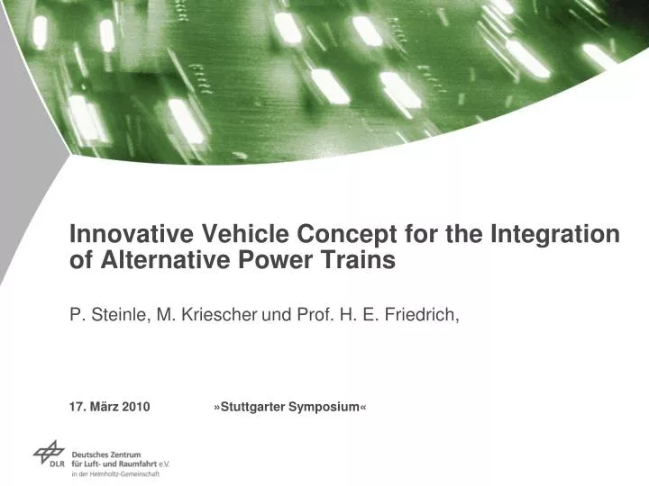
Innovative Vehicle Concept for the Integration of Alternative Power Trains P. Steinle, M. Kriescher und Prof. H. E. Friedrich,. 17. März 2010 »Stuttgarter Symposium«. Institute of Vehicle Concepts. Sites and employees of the DLR. Institute of Transport Research .

E N D
Innovative Vehicle Concept for the Integration of Alternative Power TrainsP. Steinle, M. Kriescherund Prof. H. E. Friedrich, 17. März 2010 »Stuttgarter Symposium«
Institute of Vehicle Concepts Sites and employees of the DLR Institute of Transport Research More than 6000 employees working in 27 research institutes and facilities Research Programs: • Aeronautics • Space • Transport • Energy Hamburg Bremenn Neustrelitz Trauen Berlin- Charlottenburg Braunschweign Berlin-- n Adlershof Institute of Transportation Systems nGöttingen nKöln-Porz nBonn Sankt Augustin Darmstadt nLampoldshausen nStuttgart nOberpfaffenhofen Weilheim
Table of contents • Motivation • Lightweight design strategies • General Requirements • Two different approaches • Rib and Space-Frame • Hybrid structures • Summary and Conclusion
Resources of water and oil run short Climate change can not be ignored Increasing population asks for mobility MotivationGlobal trends • Reduction of vehicle’s weight for reduced driving resistance • Less fuel consumption and CO2-emissions • Increasing efficiency • Alternative energy and storage
Shape Materials Concept Requirements Lightweight design strategies Step 1 Step 2.1 Step 2.2 Step 2.3 • Law • Customer and Market • CO2-Strategy • Package • Integration • Modularisation • Technologies • Materials • Surfaces • Processes • Shape • Geometry Source: Haldenwanger, Beeh, Friedrich
H2 CH4 e- Rib and Space-FrameRequirements – general • Law • StVZO • EG/EWG • ECE • Global (e.g. FMVSS, IIHS) • Customer and Market • Improved modularization • Scalable vehicle and propulsion system • CO2-Restrictions • Alternative Propulsion Systems (e.g. BEV, FC)
Comfort Lightweight Safety Cost Customer Acceptance Alternative Propulsion Systems Rib and Space-FrameRequirements – specific General Requirements
Detail 2 Detail 1 Detail 3 Detail 2 Detail 1 Detail 3 Vehicle ConceptsTwoDifferent approaches Higher specific energy absorption Rib-and Space-Frame • Top-Down-Method • Bottom-up-Method Lightweight and safe body structure
Fiber Reinforced Plastics Magnesium Aluminium Steel Rib and Space-FrameConcept • Alternative propulsion system (e.g. Battery) integrated into the vehicle’s floor • Continuous side members • Continuous rib structure • Crash-Elements between side members and rocker
Roof Crossbar Joint Safety-Containment for alternative propulsion systems Side member Rib and Space-Frame Mechanical principle of the rib • Basic idea: rigid B-pillar with flexural joint in the roof pillar and high performance energy absorption below the driver’s seat • Minimum deformation in the rib-structure with maximum energy absorption in the crash elements B-Pillar FCrash Part Requirements: Stiffness, Energy absorption, structural integrity
Inner Skin Omega profile Outer Skin Reinforcement Crash-cones Support Rib and Space-FrameDesign of the rib • Topology Optimization with static substitute loads • Benchmark of different materials • Interpretation and realization of the simulation results • Conversion of the generic design to the real design requirements
New design: ca. 29 kg • Reference structure: ca. 45 kg Rib and Space-FrameSimulation und Crash • Simulation and Validation of the B-Rip-Design Simulation side impact Crash test
Rib and Space-FrameMechanical principle of the Crash Compartment • Rigid structure in the middle of the vehicle • Energy absorption between rocker and side member Floor Concept: Stiffness, Energy absorption, structural integrity
x-axis Rib and Space-Frame Boundary Conditions of the Crash compartment Simplified Model Energy Absorber Equivalent masses + Crash compartment Performed Tests • Side Pole Impact according to: • EuroNCAP • FMVSS 214 • Variation along x-axis (real life safety)
y x Rib and Space-FrameGlobal Vehicle Behavior of the Crash compartment • Superposition of two different velocities between side member and rocker • Velocity 1: Translation along y-direction • Velocity 2: Translation along x-direction
Rib and Space-FrameResults of the Crash compartment • Discrete Energy absorber • Collapse according to shear forces • Continuous energy absorber • Better acceptance of shear forces • Large-scale support of the rocker • Robust against different impact scenarios Discrete structure Continuous structure Lower intrusions with the same weight
Rib and Space-FrameResults and further proceedings of the Crash compartment • Real life crash represents the worst case • Improved load carrying capacity • Reduced accelerations (compared to the discrete structure) • Further Proceeding • Different types of energy absorbers (Geometry, Material) • Integration of the floor into the energy absorption
Table of contents • Motivation • Lightweight design strategies • General Requirements • Two different approaches • Rib and Space-Frame • Hybrid structures • Summary and Conclusion
Motivation floor structure developed by DLR during SLC-project • collapse of the rocker‘s and side piece‘s cross-section during pole-crash -> energy must be absorbed by various other components • a stabilisation of the cross-section during bending should lead to a much higher weight specific energy-absorption of the rocker -> higher freedom of design and choice of materials for the surrounding structures, like the floor panels -> possibility of an overall weight reduction • the storage of critical components like Li-Ion batteries in the underbody requires a low intrusion • demand for a simple, lightweight concept made of relatively cheap materials, adaptable to different kinds of vehicle concepts
Basic principle Absorption of crash energy through elongation of material Stabilisation of cross section • stabilisation of the beam by a core structure • the core must stay intact, throughout the entire bending process, in order to increase weight specific energy absorption • simplified LS-Dyna-calculations showed an increase in weight specific energy absorption by a factor of about 2,5
Testing performed in cooperation with DOW DC 04 - beam filled with foam by the DOW chemical company hollow beam foam filled beam
Geometric variations • deformation mode stays the same for different cross sections • test with a crosssection rotated by 90 ° leads to higher peak force but earlier failure of the material -> steel with a higher max. strain would lead to even better results
Integration into the underbody structure, basic principle conventional rectangular topology: difficulty in designing an appropriate support structure a ring-like shaped, filled structure should lead to comparatively low strain values, distributed over a large portion of the structure
LS-Dyna-Simulation results with a simplified body structure • modified pole crash: • the modified pole crash was performed to avoid the addition of virtual weights • car body is fixed • weight of pole= 1380 kg • speed of pole = 29 km/h • intrusion is slightly more severe compared to a regular pole crash
Modified pole crash results with a simplified body structure • results of the new structure: • reduction of intrusion by a factor of 2,7, compared to a full vehicle with interior, even without floor panel, seat structure etc. • proof of the basic principle: the underbody structure is deformed as one „ring“, without any collapse of particular parts
Summary and conclusions • Two different approaches for lightweight and safe vehicle structures for small/medium and large scale production • DLR Rib and Space-Frame with high intrusion resistance of the B-Rip and Crash compartment • An underbody structure composed of a ring-like filled structure results in a very high intrusion resistance during pole crash. A large portion of the underbody could therefore be used for the storage of critical components like Li-Ion batteries • A more detailed car body structure is needed to make accurate weight predictions • Optimization of the structure by decreasing intrusion resistance in favor of reduced weight seems reasonable For further questions and to see a model of the car body please visit our exhibition stand