Download
1 / 50
520 likes | 760 Views
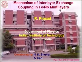
"Interlayer exchange coupling in metallic and all-semiconductor multilayered structures". OUTLINE Why are interlayer coupling phenomena interesting and Important? The explanation will be in the form of a longer story about magnetoresistance and GMR, a Nobel Prize effect.

E N D
"Interlayer exchange coupling in metallic and all-semiconductor multilayered structures" • OUTLINE • Why are interlayer coupling phenomena interesting and • Important? The explanation will be in the form of a longer • story about magnetoresistance and GMR, a Nobel Prize • effect. • Why should one study interlayer coupling effects in • all-semiconductor systems? • Why should we use neutron scattering tools for this • purpose? • What we have found so far in the course of our studies • of EuS-based all-semiconductor superlattices .
There is much written text on some slides Let me explain why. My plan is to post this Power Point Presentation on the Web. For some people it will perhaps be a useful tutorial. And, I hope, after doing some more work on it, it may also serve as sort of “propaganda movie” for informing people – e.g., prospective students -- about research conducted in our Department (we will then need a whole “package” of such slide shows, of course).
To begin, we have to go back to 1857... In 1857 Scottish scientist William Thomson, who later becomes Lord Kelvin, discovers that the application of external magnetic field to a nickel (Ni) wire increases its electric resistance. The term “magneto- resistance” is introduced for this new phenomenon. The picture shows Lord and Lady Kelvin chairing the ceremony of coronation of King Edward II in 1902. Scientist at that time were given all respect they deserved – in sharp contrast with the present situation!
After the original Kelvin’s discovery... ...physicists rushed to study other metals. Essentially, it was found that MR effects occur in any metal. For the non-magnetic ones, those findings can be summarized as a simlpe „rule of thumb”: the worse conductor the metal is, the stronger the MR effects are manifested. Bismuth (which is not even classified as a metal, but a “semimetal”) was found to be the “record-holder” – in strong magnetic fields its resistance could increase by as much as 50%. But in copper or gold the resistance changed only by a small fraction of 1%, even in very strong fields. Not surprisingly, the MR phenomena did not find too many practical applications…
Soon it was realized… …that magnetoresistance is not an effect “standing by itself”, but it belongs to a larger class of phenomena, called “galvanomagnetic effects”, or “magnetotransport effects”, which can be all described in the framework of the same theory. Another member of this class is the well-known Hall Effect.
The theory of “ordinary magnetoresitance” (OMR)andthe Hall Effectfor a simple non-magnetic metal By taking the equation of motion for electrons: And intoducing the cyclotron frequency: Standard Hall Effect Geometry: One obtains a solution in a matrix form, where the diagonal elements represent magnetoresistance, and the off-diagonal – the Hall effect:
The above theory was found to work pretty well for non-magnetic metals and semiconductords In ferromagnets(FMs), B is a non-linear function of applied field an T, showinghysteresis. However, this function can be readily determined from experi- ments. It was therefore expected that if experimental B values were used, the same theory would work well for FMs. But it did not work!! Both Hall Effect and magneto-resistance in FMs were found to behave in a highly unpredictable way. New terms were coined for them: Anomalous Hall Effect (AHE) and Anomalous MagnetoResistance (AMR).
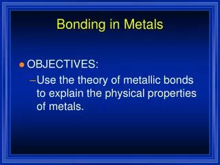
It turned out that the AHE and AMR in FM metals can only be explained on thegrounds of quantum theory. The first successful theory of AHE and AMR was created by another British scientist-aristocrat ☺, the famous Sir Nevil Mott (Nobel 1977). He asked himself: why certain transition metals – Ni, Pd, Pt – are much poorer conductors than their immediate neighbors in the Periodic Table, Cu, Ag and Au?
Here is the answer: in transition metals the current is conducted by electrons from the d-bands and s-bands (or hybrydized s+p bands) Electron in the d-bands are more tightly bound and less mobile. But the s-band electrons may be scattered by de- fects (always present) or by phonons, and may end up in the d-band, losing mobility and incre- asing the resistance. Schematic representation of the bands in a transition metal with a partially filled d-band (the bands for spin-up and spin- down electrons are shown separately).
In copper, however, the 3d band is completely filled, so such scattering cannot occur – therefore, copper is an excellent conductor!
However, in nickel, copper’s next-door neighbor, the situation is different The d-band is not completely filled, so that s→d scattering may occur, making Ni a poorer conductor There is one more important aspect: in the FM state, the situation is no longer symmetric – the 3d sub-band for only one of the spin states is now incompletely filled. This fact, it turns out, has far-reaching consequences!
“MMM” (Mott’s Motel Model) From the Mott’s picure, it follows that there are two currents: For “spin-up” current the resistance is low (no scattering). For “spin-down” current the resistance is high because such electrons may be scattered into the 3d sub-band
According to Mott’s theory, an FM conductor can be thought of as two parallel sets of resistors. By applying an external magnetic field, one can re-orient the domains, and thus change the specimen resistance – as had been originally observed by Lord Kelvin. In bulk specimens the effect is not particularly strong, though, which makes practical applications difficult ☹
W. Reed & E. Fawcett’s 1964 experimenton single-crystal iron (Fe) whiskers The result was a beautiful confimantion of the Mott model – yet, whiskers are “technologically unfriendly”
Everything grows giant these days: Pumpkins, pandas, schnauzers…. Magnetoresistance is NOT an exception! The credit for introducing the term Giant Magneto- resistanceshould be given to Dr. S. von Molnar, who used it in a 1967 paper reporting unusually strong magnetoresistance effects seen in EuSe crystals doped with Gadolinium (Gd).
However, what we call “GMR” now • is not exactly the same effect as • that observed in bulk specimens • by von Molnar et al. . • Today, “GMR” refers to an effect • occurring in nanometer-thick multi- • layered structures, discovered by • Fert (France) and P. Grünberg • (Germany), for which they were • awarded a Nobel Prize in 2007.
http://urlcut.com/German_National_Anthem Joseph Haydn, composer of The German National Anthem
Electron states in a non-magnetic metal (left) and in a ferromafnetic metal (right)
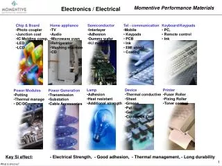
Spin valves: sophisticated GMR-based sensors The application of such sensors in the reading heads of hard-drives made it possible to increase their capacity by nearly two orders of magnitude… Since 1997, about 5 billions of such reading heads have been produced.
But the reign of GMR-based reading heads did not last long… Recently, they have been “dethroned” by even more efficient sensors utilizing another magnetoresistance effect – namely, Tunnel MagnetoResistance (TMR)
Outwardly, a TMR system is similar to a GMR one – but now the two FM conducting layers are separated by a thin (~ 1 nm)insulating layer (e.g., MgO) Ferromagnetic coupling: High tunneling probability Antiferromagnetic coupling: Low tunneling probability
However, no matter whether the sensors utilize GMR,or TMR, they always have one thing in common: Zero magnetic field ↑↑↑↑↑ Applied field ↑↑↑↑ In the initial state, the magne- tization vectors in the two FM layers must be antiparallel… ...because only then the applied field will change their mutual orientation. …then the applied field would not change their mutual orien- tation, and such system would not be sensitive to the field. If the magnetization vectors were initially parallel…
In other words… …in all types of thin film magnetoresistance sensors there has to be an interaction that couples the FM films antiferromagnetically acros the intervening non-magnetic spacer: This interaction also assures that the system returns to its initial configuration after the field is removed.
But how can one obtain a coupling of a desired sign between two FM films? Well, the whole “GMR saga” started when one day in 1986 Peter Grunberg prepa- red a “trilayer” consisting of two iron films, with a wedge-shaped non-magne- tic chromium metal layer in between. He observed that a domain pattern with alternating magnetization directions formed in the top layer, meaning that the sign of the interaction be- tween the Fe layers was an oscillating function of the Cr layer thickness. So, Grunberg’s discovery sho- wed that the desired con- figuration can be obtained by choosing an approp- riate spacer thickness.
What is the origin of the interlayer interaction with oscillating sign? There is still no consensus among researchers ragarding this issue. Some argue that it is simply the “old” RKKY interaction (known since 1950s). It couples magnetic at- oms embedded in non-magnetic metals, and its sign osc- illates with distance r . It is mediated by Fermi electrons RKKY r
Other researchers are of the opinion that Quantum Well States (QWS) play a crucial role In this model, the non-magnetic spacer is though of as a quantum well, in which electrons are confined between two “walls”, with the magnetized layers playing such a role. There are discrete E levels in such a well (recall “particle in a box”). When the well expands, these energies decrease. Each time a consecutive E level cuts through the Fermi level, the sign of the coupling changes:
But no matter who is right, there is no doubt about one point: namely, it is the conduction electrons that play a crucial role in interlayer coupling effects seen in multilayered metal- lic GMR systems. In semiconductors, in contrast, the concent- tration of conduction electrons is orders of magnitude lower than in metals. Some of them are nearly-insulating. So, the above may imply that in analogous systems made of semiconductors there is no chance of seeing interlayer coupling effects. RIGHT?!
NOT RIGHT! We have been conducting neutron scat- tering studies on all-semiconductor multilayered systems consisting of alternating magnetic and nonmagnetic layers, and in many of them we observed pronounced interlayer magnetic coupling effects.
Is it important to investigate all-semiconductor system? The existing all-metal GMR sensors are the first generation of spintronics systems. But in the opinion of many experts the future belongs to semiconductor spintronics. Such devices can be more easily integrated with existing electronics. Also, semiconductors have many highly interesting optical properties. Semicon- ductor spintronics may become an ideal partner for photonics!
There is one big problem, though. For building practical spintronics devices one would need semicondutors that are ferromagnetic at room temperature. And God did not make them. Rather, God left it as a challenge for us to create such materials synthetically. Material techno- gists in many labs worldwide continue to work hard on this problem…
Room-temperature FM semiconductors:present situation The “record-holder” now is epitaxially prepared Ga(Mn)As alloy, with about 10% of Mn. It stays FM up to 175 K – still more than 100K below the “target value”. What can be done in such situation? Well, there are some fundamental problems that need to be studied. For instance – what is the mechanism giving rise to interlayer coupling effects in sys- tems with low concentration of mobile electrons? We decided to do such studies on multilayers containing EuS, a well-known “prototypical” FM semiconductor (with Curie T of only 16 K, though).
FerromagneticEuS/PbSandEuS/YbSeSL’s EuS – Heisenberg ferromagnet TC = 16.6 K (bulk), Eg=1.5 eV PbS – narrow-gap (Eg=0.3 eV) semiconductor (n ≈ 1017 cm-3) YbSe – wide-gap (Eg=1.6 eV) semiconductor (semiinsulator) all NaCl-type structure with lattice constants: 5.968Ǻ 5.936 Ǻ 5.932Ǻ (lattice mismatch ≈ 0.5%) 4-200 Ǻ 30-60 Å number of repetitions 10-20 (001) a=6.29 Å
Neutron reflectivity experiments onthe EuS/PbS system (NG-1 reflectometer, NIST Center for Neutron Research) Situation corresponding tored data points: Situat. corresponding togreen data points: Situation corresponding toblue data points
Unpolarized neutron reflectivity experiments on the EuS/PbS system (NG-1 reflectometer, NIST Center for Neutron Research)
Alternative explanations... • PbS is a narrow-gap material. At low T the concentrations of carriers may be still pretty high. Perhaps the effect seen in EuS/PbS is a carrier-mediated coupling? • Crucial test: make a EuS/XY system, in which XY is a wide-gap semiconductor or an insulator • An ideal material, YbSe was found for that purpose.
Interlayer exchange coupling mediated by valence band electrons J.Blinowski & P.Kacman, Phys. Rev. B 64 (2001) 045302. P.Sankowski & P.Kacman, Acta Phys. Polon. A 103 (2003) 621
Unpolarized neutron reflectivity experiments on the EuS/YbSe system(NG-1 reflectometer, NIST Center for Neutron Research)
CLOSING REMARKS • It is good to inspiration from the work of others. If these people got a Nobel Prize, it would add prestige to your work! ☺ • Now, more seriously: Metal-based spintronics has a bright future. One new application that is emerging is generating GHz signals, which may lead to further progress in cellullar phone technology. • Semiconductor spintronics will more likely utilize TMR than GMR. Note that in a TMR device the FM films are separated by an insulating spacer. From that standpoint, our work makes much sense – essentially, what we are doing, is studying interlayer coupling between FM films across insulating spacers. Las fall, for example, we made measurements on system in which EuS layers are separated with barriers of SrS, which has energy gap width 4.6 eV, making it a perfect insulator. And we saw pronounced antiferromagnetic interlayer coupling in those systems.