Download
1 / 70
750 likes | 888 Views
PMAC-NC Standard Header Files, PLCs and Motion Programs. Introduction.

E N D
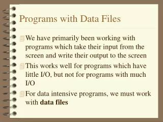
Introduction PMAC-NC requires a set of files to provide the basic functionality for the machine tool. Some may be modified to fit the system specific requirements of the machine and/or supplemented with those written by the integrator. These consist of header files, PLCs and motion programs. The header files and PLCs will be the main topic of this class.
Summary of Course • What are header files and how are they used in the PMAC-NC system. • What are the basic PLCs for PMAC-NC and how are they tailored for individual systems. • What additional PLCs will need to be written to augment the functionality of the provided PLCs.
Header Files A header file, or include file, was developed in C to allow programmers to write better code by providing the ability to define commands with user defined macros. The CNC AutoPilot uses MACROs in the modular file structure system it creates. This helps in documentation and better control of the machine software.
Header Files (cont.) It is strongly recommended that you only make changes to the header files where indicated. Sections of certain header files have been set aside for the integrator to modify. These files are closely tied to the user interface software and incorrect mod-ifications will impair PMAC-NC.
Header Files (cont.) PMAC-NC uses header files for the assignment of DP Ram addresses between the PMAC and host. It also provides Macro definitions for many of the PMAC variables used. The header files are installed in the directory specified in the AutoPilot application. The main header files are Address.H and OEM.H. Their directory is “pathed” so the files are accessible from any directory. These two files should never be modified.
Header Files A macro definition is nothing more than a substitution name which is used in place of any valid PMAC command as in GATHER or DWELL, command phrase such as OPEN PROG 1 or M1->Y:$78C00,0,1. Or as variable reference like P1, M22, Q3042, etc..
Header Files Macro definitions are declared at the beginning of the program file using the “#define” pre-processor command. #define pressure P1 #define turn_on_Board1_Bit0 M1=1 #define collect_data GATHER #define seconds NULL
Header Files (cont.) The header files are used by “including” them in the project file as follows: #include "address.h" When you use additional header files, you will need to put them in the directory created by the CNC AutoPilot or use a full path in the “include” statement. #include “c:\MyMachine\mymacros.h"
Header Files (cont.) It is a good practice to put all of your variable assignments and macros in one file and include that file where needed. Example: #include "c:\cnc\mill\ MyMachine.H " This makes debugging your code and upgrading versions of PMAC-NC easier.
The Basic PMAC-NC Files • NC_I_VAR.IVR This file stores all the I-Variables generated by AutoPilot program using the Machine Setup input. • INITIALIZE.PLC This is a one-time execution PLC. This is used to initialize the NC system variables or I/O. Additional variables can be placed in this file. • CNTLPANEL.PLC This is the control panel PLC for Adv 810/900. • OVERRIDE.PLC This is the percentage override control PLC used for spindle and feed rate.
The Basic PMAC-NC PLCs • HOME.PLC This is the home PLC for all axes. • HANDLE.PLC This PLC is for the handwheel function. • SPINDLE.PLC This PLC is for spindle. It can be open or closed. • Reset.PLC This is template PLC for Reset action. User can add RESET sequence or any other Reset related action in this PLC.
The Basic PMAC-NC PLCs • GPTimer.PLC This PLC provides additional Timers by using PMAC free memory locations. • POSITION_REPORT.PLC This is the user position reporting PLC generated only if the User Position Reporting check box is selected. • OEM.H This header file is created by the AutoPilot program based on user input and should not be altered. The MyMachine.H file is for general use.
The Basic PMAC-NC PLCs • NCPLC.H The AutoPilot program generates this file based on the user input. It consist of the macros for MILL.G, MILL.M, and MILL.T (the G, M, and T code files) used in the application. • ADVCNTLU.H This file is in C:\Program Files\Common Files\Delta Tau Shared folder and should not be altered. This will be useful in assigning user buttons on the Adv 810/900 control panel. • IO810.H or IO600.H This file is an input output file. The IO810 header file is for the Adv 810 and IO600 is for an Adv 600 type controller. These files can be modified as needed and are found in C:\Program Files\Delta Tau\PmacNC\Mill.
Control Panel PLC This is the control panel Initialization of variables section. It runs once being outside the infinite while loop. OPEN PLC CONTROL_PANEL CLEAR // Set the Home Method - User Input ------- HOME_MODE_P = HOME_MODE // Standard Initialization of variables ------- SINGLE_BLOCK_FLAG = OFF BLOCK_DEL_FLAG = OFF OPT_STOP_FLAG = OFF . . .
Control Panel PLC . . . S_SPND_M = SEL_SPND_OFF C_COORD_M = 0 S_COORD_M = 0 // Default Mode Inch - so RESET METRIC MODE BIT for NC. ------- @SET_OFF(CS_STATUS6_M,CS_METRIC_MODE) VS_GGROUP6_1_M = 20 // Actual PLC Infinite Loop ------- WHILE(1>0)
Control Panel PLC Usually the Isx87= TA time should at least be equal to Isx13 time. If it is found that Isx87 is less than Isx13 then this PLC will set Isx87 to the default value. The user can set the default acceleration time. //------------------------------------------------------------ // Actual PLC Infinite Loop ------- WHILE(1>0) //------------------------------------------------------------ IF (I5187 < I5113) I5187 = I5113 // Default Value User can change this. // I5187 = DEFAULT_ACC_TIME ENDIF
Control Panel PLC Mode selection logic IF (PB_MDI_M = 1 AND S_MODE_M != SEL_MODE_MDI) C_MODE_M = SEL_MODE_MDI ELSE IF (PB_AUTO_M = 1 AND S_MODE_M != SEL_MODE_AUTO) C_MODE_M = SEL_MODE_AUTO ELSE IF (PB_MANUAL_M = 1 AND S_MODE_M != SEL_MODE_MANUAL) C_MODE_M = SEL_MODE_MANUAL ENDIF ENDIF ENDIF
Control Panel PLC Switch to Auto or MDI Mode if Motion program is not running. . . . IF (C_MODE_M > 0) IF (C_MODE_M != S_MODE_M) IF (C_MODE_M = SEL_MODE_AUTO OR C_MODE_M = SEL_MODE_MDI) IF (PROG_RUNNING_M = 0 AND IN_POSITION_M = 1) OR(FEED_HOLD_M = 1) CMD^A CMD"&1B0" S_MODE_M = C_MODE_M C_SPND_M = SEL_SPND_OFF ENDIF ENDIF . . .
Control Panel PLC Switch to manual mode . . . IF (C_MODE_M = SEL_MODE_MANUAL) CMD^A S_MODE_M = C_MODE_M S_JOG_M = C_JOG_M ENDIF ENDIF . . .
Control Panel PLC Switch to manual mode or finally resettheModecommand . . . IF (C_MODE_M = SEL_MODE_MANUAL) CMD^A S_MODE_M = C_MODE_M S_JOG_M = C_JOG_M ENDIF ENDIF C_MODE_M = 0 ENDIF . . .
Control Panel PLC Continuous JOG PLUS for selected - axis first check for allowed state. . . . IF(PB_JOG_PLUS_M=1 OR PB_JOG_MINUS_M=1 OR @ON(CS_COMMAND3_M,CS_JOG_PLUS) OR @ON(CS_COMMAND3_M,CS_JOG_MINUS)) AND(@OFF(CS_COMMAND3_M,CS_JOG_STOP) AND S_MODE_M = SEL_MODE_MANUAL) IF (PROG_RUNNING_M=0 AND IN_POSITION_M = 1) OR(FEED_HOLD_M=1) . . .
Control Panel PLC Continuous JOG PLUS for selected axis - then check for axis selected and execute jog command. JOG MINUS has similar code. . . . IF (PB_JOG_PLUS_M=1 OR @ON(CS_COMMAND3_M,CS_JOG_PLUS)) AND (S_JOG_M = SEL_JOG_CONT) IF (JOG_PLUS_FLAG = 0 AND PB_JOG_MINUS_M=0 AND HOMING_ACTIVE_FLAG=0) IF (C_AXIS_M=SEL_AXIS_X) JOG_X_PLUS @SET_ON(CS_STATUS3_M,CS_JOG_PLUS) @SET_OFF(CS_STATUS3_M,CS_JOG_STOP) ELSE IF (C_AXIS_M=SEL_AXIS_Y) JOG_Y_PLUS @SET_ON(CS_STATUS3_M,CS_JOG_PLUS) @SET_OFF(CS_STATUS3_M,CS_JOG_STOP) . . .
Control Panel PLC When jog is complete – clear status and reset flags . . . IF(JOG_PLUS_FLAG = 1 OR JOG_MINUS_FLAG = 1 OR @ON(CS_COMMAND3_M,CS_JOG_STOP)) JOG_STOP_ALL @SET_ON(CS_STATUS3_M,CS_JOG_STOP) @SET_OFF(CS_COMMAND3_M,CS_JOG_STOP) @SET_OFF(CS_STATUS3_M,CS_JOG_MINUS) @SET_OFF(CS_STATUS3_M,CS_JOG_PLUS) @SET_OFF(CS_COMMAND3_M,CS_JOG_MINUS) @SET_OFF(CS_COMMAND3_M,CS_JOG_PLUS) ENDIF JOG_PLUS_FLAG = 0 JOG_MINUS_FLAG = 0 ENDIF . . .
Control Panel PLC CYCLE START SECTION . . . IF (S_MODE_M != SEL_MODE_MANUAL) IF (PB_CYCLE_START_M=1) OR (@ON(CS_COMMAND3_M,CS_CYCLE_START)) IF (CYCLE_START_FLAG=0) IF (HOME_COMPLETE_1_M = 1 AND HOME_COMPLETE_2_M = 1 AND HOME_COMPLETE_3_M = 1) IF (PROG_RUNNING_M=0 AND IN_POSITION_M = 1) OR (FEED_HOLD_M=1) @START_TIMER(TIMER_1_M,5000) IF (@TIMER_RUNNING(TIMER_1_M)) IF (@OFF(CS_STATUS3_M,CS_SINGLE_BLOCK)) CMD"&1 R" . . .
Override PLC • Works in conjunction with the control panel PLC to set feedrate overrides based on hardware value and machine operation. • Controls Time base Mode, Slew Rate, and Time base Units. • It is highly recommended that you do not change this PLC.
Override PLC • Time Base - PMAC’s working frequency which can be adjusted for faster or slower proportional execution. • Time Base Pointer (Isx93) - Address PMAC points to for time-base value. • Time Base Units (Isx90) - Time-base units specified in milliseconds. • Slew Rate (Isx94) - Rate of time-base changes.
Override PLC (cont.) • Calculate Time Base using Override. • For Rapid and Cutting Modes set Slew to Regular (Med) and for FPR and Thread Modes set to maximum. • For FPR, set time base units from minutes to the appropriate scaled value. • Set Time Base to Cutting, Rapid, Thread, or FPR (Exact).
Override PLC (Calculate TB) CUTTING _TIMEBASE_M = VS_FEED_OVERRIDE_M * 0.01 * I10 RAPID _TIMEBASE_M = VS_RAPID_OVERRIDE_M * 0.01 * I10 CUTTING_TIMEBASE_M M362->X:$2000,0,24,S This address holds the C.S. 1 “%” register for override value. RAPID_TIMEBASE_M M364->X:$10F2,0,24,S I10 units, Open usage register
Override PLC (Calculate TB) FPR_TIMEBASE_M = SPND_TIMEBASE_M * 0.01 * VS_FEED_OVERRIDE_M FPR_TIMEBASE_M M369->X:$0010F4,0,24,S SPND_TIMEBASE_M M370->X:$00350A,0,24,S This address holds the time base scale factor from the encoder conversion table for the spindle encoder
Override PLC (Set Slew) Set Slew Rate depending on Time Base • Cutting and Rapid modes function best with gradual changes of velocity. I5194 = 4250. TIME_BASE_SLEW_I = MED_SLEW • FPR and Thread need to react immediately to changes. I5194=8,388,607 (max value) TIME_BASE_SLEW_I = MAX_SLEW
Override PLC (Set Unit) • For Rapid, Cutting and Thread modes set units to minutes. CS1_TIMEBASE_UNITS_I = MINUTES_MS • For FPR mode set units to revolutions. CS1_TIMEBASE_UNITS_I = MINUTES_MS / VS_SPINDLE_MAX_LIM_M
Override PLC (Assign TB) • Select appropriate time base and write to DPR. (from address.h) S_TIMEBASE_M = SEL_TIMEBASE_CUTTING S_TIMEBASE_M M76->Y:$6CDE4,4,4,U SEL_TIMEBASE_CUTTING 0 SEL_TIMEBASE_RAPID 1 SEL_TIMEBASE_THREADING 2 SEL_TIMEBASE_EXACT 3
Override PLC (Assign TB) • Assign register directly to I5193, based on address map of S/W Ref. TIMEBASE_M = CUTTING_TIMEBASE TIMEBASE_M = FPR_TIMEBASE TIMEBASE_M M360-> X:$2001,0,20,U (I5193) FPR_TIMEBASE $10F4 CUTTING_TIMEBASE $2000
Handwheel PLC • Controls movement based on MPG or Handwheel input. • Initializes position, jog speed, and feedrate override. • Moves axis until handwheel request has been satisfied. • Restores jog speeds and feedrate.
Handwheel PLC (cont.) If the machine is in manual mode and handwheel is selected, this PLC initializes handle counts, target position, scaling multiplier and handwheel jog speed, then enables loop. PREV_HANDLE_COUNT = HANDLE_COUNT_M TARGET_POS_1_M = DESIRED_POS1_M/(I108*32) HANDLE_FACTOR_1=PULSES_PER_UNIT_1/400 PREV_1_JOG_SPEED = I122 INIT_HANDLE = TRUE
Handwheel PLC (cont.) // If mode is set for handwheel enter while loop. Set feed override to 100%, delay for TA for FO to take effect, set jog speed for handwheel and initialize counts. VS_FEED_OVERRIDE_M = 100.0 @START_TIMER(TIMER_1_M,70) WHILE (@TIMER_RUNNING(TIMER_1_M)) ENDWHILE I122 = 100 HANDLE_CHANGE = (HANDLE_COUNT_M - PREV_HANDLE_COUNT)%-32768 PREV_HANDLE_COUNT = HANDLE_COUNT_M
Handwheel PLC (cont.) During while loop, update target position by adding the scaled handwheel input to the current position and commanding a jog for the appropriate axis. Then, exit the while loop. IF (S_AXIS_M = SEL_AXIS_X AND HANDLE_CHANGE != 0) IF (PLUS_LIMIT1_M = 1 AND HANDLE_CHANGE > 0) HANDLE_CHANGE = 0 ENDIF IF (NEG_LIMIT1_M = 1 AND HANDLE_CHANGE < 0) HANDLE_CHANGE = 0 ENDIF TARGET_POS_1 = TARGET_POS_1 + VS_HAND_STEP_M*HANDLE_FACTOR_1*HANDLE_CHANGE TARGET_POS1_M = TARGET_POS_1+ POS_BIAS1_M/(I108*32) JOG_X_INCR //CMD”#1J=*” ENDIF
Handwheel PLC (cont.) On exiting while loop, reset loop enabling to false, restore previous jog speed and set commanded feedrate to 0. IF (INIT_HANDLE = TRUE) INIT_HANDLE = FALSE I122 = PREV_1_JOG_SPEED C_FEED_M = 0 ENDIF
Spindle PLC • Can be configured for either closed or open loop control, closed is default. • Initializes variables and issues commands to put spindle into a known state. • Runs in loop updating spindle information, arming triggers, and commanding spindle velocity.
Spindle PLC (cont.) Set the counts per revolution of the spindle, counts per revolution of the X axis, the maximum RPM (from AutoPilot entries), and the tolerance in RPM to consider the spindle at speed. VS_SPINDLE_COUNTS_REV_M = 2000 // Spindle VS_SPINDLE_CSS_UNITS_M = 25400 // X-Axis VS_SPINDLE_MAX_RPM_M=6000 VS_SPINDLE_MAX_LIM_M=6000 SPINDLE_ERR_ALLOWED=35 // in RPM
Spindle PLC (cont.) • For open loop spindles AutoPilot points the DAC output variable to an unused register. I402 = $10F5 • For each system the integrator will need to determine the ratio of volts to RPMs for the spindle. Maximum Voltage/Maximum RPM VOLTS_PER_RPM = 10/6000
Spindle PLC (cont.) Issue spindle a stop command, set commanded speed 0, set spindle feedrate override to 100% and insure spindle is in FPM mode. VS_SPINDLE_OVERRIDE_M=100 C_SPND_M = SEL_SPND_OFF @SET_OFF(CS_COMMAND3_M,CS_SPND_AT_SPEED) @SET_OFF(CS_COMMAND3_M,CS_SPND_AT_ZERO) @SET_OFF(CS_COMMAND3_M,CS_SPND_FEED) @SET_OFF(CS_COMMAND3_M,CS_SPND_CSS)
Spindle PLC (cont.) • Enable processing loop after initialization is complete and begin regular update routine. SCAN = TRUE • Calculate the RPM by converting the actual velocity of motor 4 (register X:$21D, see the S/W Ref) to RPMs. VS_SPINDLE_ACT_RPM_M = ABS (SPINDLE _MOTOR_VEL) / (I409*32) * 8388608/I10 * 60000 / VS_SPINDLE_COUNTS_REV_M
Spindle PLC (cont.) • Set the spindle at zero bit at 5 RPMs or less. IF ( VS_SPINDLE_ACT_RPM_M < 5 ) @SET_ON(CS_STATUS3_M,CS_SPND_AT_ZERO) ELSE @SET_OFF(CS_STATUS3_M,CS_SPND_AT_ZERO) • If timebase is frozen then arm for threading. IF(THREAD_PROC_BITS_M = $90) THREAD_PROC_BITS_M = $B0
Spindle PLC (cont.) • Monitor for spindle off command, set last direction to stop and execute stop sequence. IF(S_SPND_M = SEL_SPND_OFF ) LAST_SPND_DIR = SEL_SPND_OFF • For closed loop spindle, issue a #4j/. JOG_STOP
Spindle PLC (cont.) For open loop set DAC to 0 output plus the DAC bias, thereby reducing the effective output to 0 volts; wait for friction to slow spindle and disable spindle when moving at less than 5 RPMs. SPINDLE_DAC_M = 0 + I429 IF ( VS_SPINDLE_ACT_RPM_M < 5 ) SPINDLE_ENA_M = 0 ENDIF
Spindle PLC (cont.) • Only execute the rest of the PLC if movement is commanded for the spindle. • Based on spindle’s speed, set the “at speed” bit. IF( ABS(VS_SPINDLE_ACT_RPM_M - VS_SPINDLE_CMD_RPM_M) < SPINDLE_ERR_ALLOWED ) @SET_ON(CS_STATUS3_M,CS_SPND_AT_SPEED) ELSE @SET_OFF(CS_STATUS3_M,CS_SPND_AT_SPEED)
Spindle PLC (cont.) • For CSS, calculate radius of X axis in counts and insure the value is not zero. IF(@ON(CS_STATUS3_M,CS_SPND_CSS)) SPINDLE_CSS_RADIUS = ABS((SPINDLE_CSS_POS + POS_BIAS1_M) / (I108 * 32) - VS_X_ABS_M * VS_SPINDLE_CSS_UNITS_M) / VS_SPINDLE_CSS_UNITS_M IF(SPINDLE_CSS_RADIUS < 0.0001) SPINDLE_CSS_RADIUS = 0.0001 ENDIF
Spindle PLC (cont.) Calculate basic commanded RPM by converting VS_SPINDLE_CSS_M, the specified surface speed in FPM or MPM, from user units to counts and then dividing by the circumference. IF(@OFF(CS_STATUS6_M,CS_METRIC_MODE)) SPINDLE_TEMP = (12.0 * VS_SPINDLE_CSS_M) / (2 * 3.14159272 * SPINDLE_CSS_RADIUS)