Download
1 / 30
300 likes | 785 Views
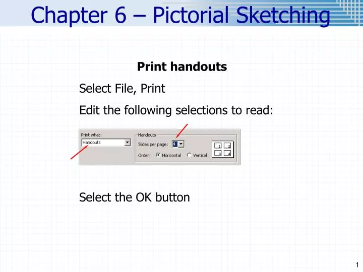
Print handouts Select File, Print Edit the following selections to read: Select the OK button. Chapter 6 – Pictorial Sketching . Chapter 6 – Pictorial Sketching . Projection Systems . Page 169. Multiview vs Axonometric Projection. Page 170, Figure 6.2. Overview.

E N D
Print handouts Select File, Print Edit the following selections to read: Select the OK button Chapter 6 – Pictorial Sketching
Projection Systems Page 169
Multiview vs Axonometric Projection Page 170, Figure 6.2
Overview • Previous discussion centered on multiview drawings -2D orthographic projections (Chap 5) • Focus now on pictorial drawings which look more like pictures than a multiview drawing (3D). • Easier to visualize design • Sometimes added to multiview drawing for clarification • Good for marketing, shows assembly, inspect fits, conceptual ideas • Not good for dimensioning/manufacturing (can’t show detail)
Exploded Isometric Assembly Isometric drawings are frequently used to show how parts assemble as in this automobile power module.
Axonometric Projections • We will focus on isometric sketching. • Note, all angles are equal, and all line segments are equal (cube) Page 154
Isometric Projection vs. Sketch Page 155 Isometric projections are foreshortened because the object is tipped with respect to the viewing plane. Isometric sketches, or drawings, are not usually foreshortened because they still appear proportionate when showing the dimensions full size along isometric axis lines. It is easier just to sketch the full dimension.
Step by Step: Isometric Sketching Page 156
Axis, Views and Dimensions 3D - Isometric Axis? Views? Top Top Front R Side Front R Side 2D - Orthographic
Axis, Views and Dimensions 3D - Isometric Axis? Views? Top Top Front R Side Front R Side 2D - Orthographic
Axis, Views and Dimensions 3D - Isometric Axis? Views? Dimensions? Top Top Depth H Front R Side Width D W Isometric Line Isometric Plane Height Front R Side 2D - Orthographic
Hidden Lines Hidden lines are not usually shown in isometric sketches unless they are needed to show a feature that would be unclear. Usually the orientation for the isometric drawing should be chosen so that hidden lines aren’t needed. Holes are assumed to go completely through the object unless their depth is indicated with a note or with hidden lines.
Isometric Lines H Isometric Plane D Non-isometric Line W W D H 1st Position Axis: 1st Position VS 2nd Position 1. Box in overall dimensions. 2. Which view is most descriptive? Sketch as much of it as you can. Non-isometric Plane 2nd Position
Solid Modeling Demo • Pro/ENGINEER (planes)
Example ¼” GRID
Locating Features Page 158 To locate a feature such as the upper block, make measurements from an existing corner as shown here.
0, 0, 0 0, 0, 0 Plotting Points 1. Number the plane you want to locate. 2. Number the plane in the other views. 3. Locate the plane in the isometric view point by point. 1 Point 1: .5, 1.5, .5 • 4 • 2 1 2, 3, 1,4 1, 2 4, 3 0, 0, 0 W, H, D
Plotting Points 1. Number the plane you want to locate. 2. Number the plane in the other views. 3. Locate the plane in the isometric view point by point. 2 1 Point 1: .5, 1.5, .5 • 4 • 2 1 Point 2: 1.5, 1.5, .5 0, 0, 0 2, 3, 4, 1 1, 2 4, 3 0, 0, 0 0, 0, 0
Plotting Points 1. Number the plane you want to locate. 2. Number the plane in the other views. 3 3. Locate the plane in the isometric view point by point. 2 4 1 Point 1: .5, 1.5, .5 • 4 • 2 1 Point 2: 1.5, 1.5, .5 Point 3: 1.5, 1.5, 1 Point 4: .5, 1.5, 1 0, 0, 0 2, 3, 4, 1 1, 2 4, 3 0, 0, 0 0, 0, 0
Plotting Points 1. Number the plane you want to locate. 2. Number the plane in the other views. 3 4’ 3. Locate the plane in the isometric view point by point. 2 1’ 4 1 Point 1: .5, 1.5, .5 • 4 • 2 1 , 4’ Point 2: 1.5, 1.5, .5 Point 1’: .5, 2, .5 , 1’ Point 4’: .5, 2, 1 0, 0, 0 1’, 4’ 2, 3, 1,4 1, 2 4, 3 0, 0, 0 0, 0, 0
3’ 2’ Plotting Points 1. Number the plane you want to locate. 2. Number the plane in the other views. 3 4’ 3. Locate the plane in the isometric view point by point. 2 1’ 4 1 Point 1: .5, 1.5, .5 • 4 • 2 1 , 3’ , 4’ Point 2: 1.5, 1.5, .5 Point 2’: 1.5, 2, .5 , 2’ , 1’ Point 3’: 1.5, 2, 1 0, 0, 0 2’, 1’, 4’ 3’ 2, 3, 4, 1 1, 2 4, 3 0, 0, 0 0, 0, 0
Plotting Points 1. Number the plane you want to locate. 3’ 2. Number the plane in the other views. 2’ 4’ 3. Locate the plane in the isometric view point by point. 2 1’ 4 1 Point 1: .5, 1.5, .5 • 4 • 2 1 , 3’ , 4’ Point 2: 1.5, 1.5, .5 Point 2’: 1.5, 2, .5 , 2’ , 1’ Point 3’: 1.5, 2, 1 0, 0, 0 2’, 1’, 4’ 3’ 2, 3, 4, 1 1, 2 4, 3 0, 0, 0 0, 0, 0
Plotting Points 1. Number points. 2. Locate axis (0,0,0) (W,H,D) 3’ 3. Locate each point. 4. Connect points. 3 1’ 5. Darken appropriate lines. 2’ 1’ 3’ 2’ 1 2 3 2 1 3, 3’ 1, 1’ Point 1? .75, 2, 0 Point 3? 2, 2’ 1.5, 2, 0 Points 1,’, 2’, & 3’? Point 2? 1.5, 1.25, 0
Plotting Points 1. Number points. 2. Locate axis (0,0,0) (W,H,D) 3’ 3. Locate each point. 4. Connect points. 3 1’ 5. Darken appropriate lines. 2’ 1’ 3’ 2’ 1 2 3 2 1 3, 3’ 1, 1’ Point 1? .75, 2, 0 Point 3? 2, 2’ 2.25, 2, 0 Points 1,’, 2’, & 3’? Point 2? 1.5, 1.25, 0
Inclined Surfaces in Isometric Page 157 Inclined surfaces can not be measured along inclined lines in an isometric sketch. To locate inclined surfaces you must make measurements along the isometric axis lines.
Locating on a Non-isometric Plane Locate the center of the circle. .5, 1.0625, .75 Point 1 coordinates? 1 1 1 1
Complete the Isometric Point 1: 0, 0, .625 .625, .5, 1.375 Point 2: Point 3: .625, ..5, 625 0, 0, .1.375 Point 4: • 3 4 • 2 1 3 2 4 1 • 2 3 • 1 4 2, 3 1, 4
Complete the Isometric Point 1: 0, 0, .625 .625, .5, 1.375 Point 2: Point 3: .625, .5, 625 0, 0, .1.375 Point 4: • 3 4 • 2 1 3 2 4 1 • 2 3 • 4 2, 3 1, 4
Sketching • Lightly show all construction lines (or you will loose points)