Download
1 / 7
70 likes | 150 Views
General Case. Adapted from Hall, Hall and McCall, “High-Speed Digital System Design,” p.121 “Orange polygon” is Arpad’s SPICE model. PWR (3.3 V). Lpwr_rcv. Lpwr_drv. rcv_bw. drv_bw. drv_pwr. rcv_pwr. 0.01. Lline_rcv. Lline_drv. drv_out. rcv_in. drv_gnd. rcv_gnd. Lgnd_drv.

E N D
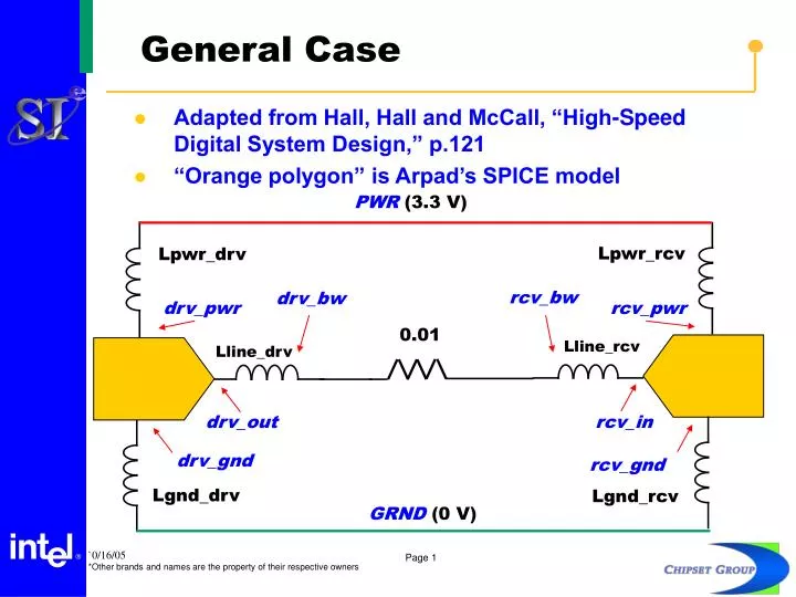
General Case • Adapted from Hall, Hall and McCall, “High-Speed Digital System Design,” p.121 • “Orange polygon” is Arpad’s SPICE model PWR (3.3 V) Lpwr_rcv Lpwr_drv rcv_bw drv_bw drv_pwr rcv_pwr 0.01 Lline_rcv Lline_drv drv_out rcv_in drv_gnd rcv_gnd Lgnd_drv Lgnd_rcv GRND(0 V)
Cases 1 & 7 • Lpwr_drv = 9 nH • Lgnd_drv = 7.5 nH • Lpwr_rcv = 9 nH • Lgnd_rcv = 7.5 nH • Lline_drv = 9 nH • Lline_rcv = 9 nH PWR (3.3 V) Lpwr_rcv Lpwr_drv rcv_bw drv_bw drv_pwr rcv_pwr 0.01 Lline_rcv Lline_drv drv_out rcv_in drv_gnd rcv_gnd Lgnd_drv Lgnd_rcv GRND(0 V)
Cases 2 & 8 • Lline_drv = 16.5 nH • Lline_rcv = 16.5 nH • K_drv = 0.45454545 • K_rcv = 0.45454545 • Lpwr_drv = 16.5 nH • Lgnd_drv = 0 nH • Lpwr_rcv = 16.5 nH • Lgnd_rcv = 0 nH PWR (3.3 V) Lpwr_rcv Lpwr_drv rcv_bw drv_bw rcv_pwr drv_pwr K K 0.01 Lline_rcv Lline_drv drv_out rcv_in drv_gnd rcv_gnd Lgnd_drv Lgnd_rcv GRND(0 V)
Cases 3, 5, 9 & 11 • Lline_drv = 9 nH • Lline_rcv = 9 nH • K_drv = 0 • K_rcv = 0 • Lpwr_drv = 9 nH • Lgnd_drv = 9 nH • Lpwr_rcv = 9 nH • Lgnd_rcv = 9 nH PWR (3.3 V) Lpwr_rcv Lpwr_drv rcv_bw drv_bw rcv_pwr drv_pwr K K 0.01 Lline_rcv Lline_drv drv_out rcv_in drv_gnd rcv_gnd Lgnd_drv Lgnd_rcv GRND(0 V)
Cases 4, 6, 10 & 12 • Lline_drv = 18 nH • Lline_rcv = 18 nH • K_drv = 0.5 • K_rcv = 0.5 • Lpwr_drv = 18 nH • Lgnd_drv = 0 nH • Lpwr_rcv = 18 nH • Lgnd_rcv = 0 nH PWR (3.3 V) Lpwr_rcv Lpwr_drv rcv_bw drv_bw rcv_pwr drv_pwr K K 0.01 Lline_rcv Lline_drv drv_out rcv_in drv_gnd rcv_gnd Lgnd_drv Lgnd_rcv GRND(0 V)
Settings & Results • All cases run in HSPICE 2005.09 • No transmission lines used • Other settings varied include • RMAX • METHOD • Timestep • Correction from previous: Receiver nodes connected to local supplies, not to universal PWR and GND Receiver input pad vs. receiver local ground
Decks • Decks are embedded below….