Download
1 / 50
510 likes | 629 Views
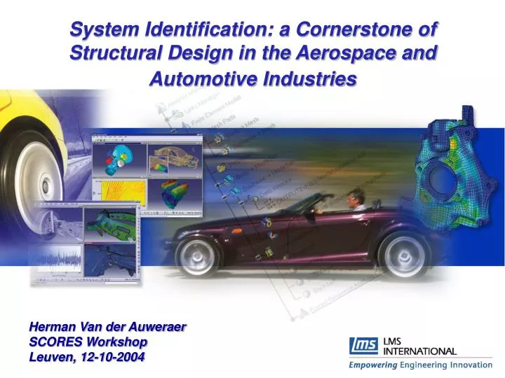
System Identification: a Cornerstone of Structural Design in the Aerospace and Automotive Industries. Herman Van der Auweraer SCORES Workshop Leuven, 12-10-2004. Overview. Objective: To discuss the vital importance of System Identification in the Mechanical Design Engineering Process

E N D
System Identification: a Cornerstone of Structural Design in the Aerospace and Automotive Industries Herman Van der Auweraer SCORES Workshop Leuven, 12-10-2004
Overview • Objective: To discuss the vital importance of System Identification in the Mechanical Design Engineering Process • To identify the specific challenges for this kind of problems and to illustrate the research needs • Illustrate with typical products: cars,aircraft, satellites, …. where adequate mechanical product behaviour is vital
Overview • Introduction: the role of Structural Dynamics in Mechanical Design Engineering • Approach and methodology for Structural Dynamics Analysis: Experimental Modal Analysis • Modal Parameter Identification methods • Applications of modal analysis • Recent evolutions and challenges for the future • Conclusions
IntroductionMechanical Design Engineering • Market Demand: Delivering products with the required mechanical characteristics: Excel in • Operational quality (performance specifications…) • Reliability (load tolerance, fatigue, life-time…) • Safety (vehicle crash, aircraft flutter….) • Comfort (noise, vibration, harshness) • Environmental impact (emissions, waste, noise, recycling…) • Process process challenges: Excel in • Time-to-Market: reduce design cycle • Reduce design costs • Product customization
Introduction Economic Impact: Some Figures • Typical vehicle development programs require investment budgets of 1 .. 4 B$ • New Mercedes C-class (Automotive Engineering Intl., Aug. 2000): • 600 M$ development + 700M$ production facilities • Developed in less than 4 years • New Mini: 200M£ development costs(+ as much in marketing...) • Chrysler minivan (“The Critical Path” by Brock Yates): • 2 B$ development budget, of which 250 M$ R&D • 36 different body styles, 2 wheelbases, 4 engines
IntroductionTime Pressure Increases Recall Risks • Warranty costs may explode the overall budget • 2000 warranty cost (Mercedes-Benz) : 1.5 b$ • Warranty cost exceeds R&D cost • Warranty cost x 3 in 2 years ...
IntroductionMechanical Design Engineering • Early Design Optimization is Essential • Product design has to go beyond the “Form and Fit” • Focus on “Functional Performance Engineering” • For mechanical performances: structural analysis • Static: strength, load analysis • Kinematic: mechanisms, motion • Dynamic: vibrations, fatigue, noise • Basic approach: is through the use of structural models • A priori (Finite Element) and experimental (Modal) • Analyze the effect of dynamic loads • Understand the intrinsic structural dynamics behaviour • Derive optimal design modifications
Introduction: A Systems ApproachA Source-Transmitter-Receiver Model TACTILE Engine Steering Wheel Shake Total Vehicle System Seat Vibration Wheel & Tire Unbalance VISUAL Rearview mirror vibration Road Input Accessories Environmental Sources Noise at Driver’s & Passenger’s Ears ACOUSTIC System Transfer Source Receiver = X
Overview • Introduction: the role of Structural Dynamics in Mechanical Design Engineering • Approach and methodology for Structural Dynamics Analysis: Experimental Modal Analysis • Modal Parameter Identification methods • Applications of modal analysis • Recent evolutions and challenges for the future • Conclusions
Experimental Modal AnalysisPrinciples f x x x f (t) f (t) (t) (t) (t) (t) n 1 2 1 n 2 k k 2 k n+1 1 m m m ground ground n 1 2 c c n+1 c 2 1 • Structural dynamics modelling: relating force inputs to displacement/acceleration outputs • Multiple D.o.F. System: • Continuous structures approximated by discrete number of degrees of freedom -> Finite Element Matrix Formulation • Majority of methods and applications: Linear and Time-Invariant models assumed
Experimental Modal AnalysisPrinciples • Modal Analysis: Related to Eigenvalue Analysis • Time domain equation • Laplace domain equation • Eigenvalue analysis -> system poles and Eigenvectors • System pole -> Resonance frequency and damping value • Eigenvector -> Mode shape • Transformation vectors to “Modal Space”
Experimental Modal AnalysisPrinciples • Modal Shape: Eigenvector in the physical space: physical interpretation (Example “Skytruck”)
Modal Analysis Principle;Decomposition in Eigenmodes • Modal Analysis: The modal superposition a1 a2 x x + … + = + … + + a3 a4 x x
Experimental Modal AnalysisPrinciples • Modal Analysis: An input/output relation • Transfer Function Formulation: • Model reduction (Finite number of modes):
Experimental Modal AnalysisPrinciples y(t) Y(ω) u(t) U(ω) H • Experimental Analysis: using input/output measurements • Non-parametric estimates (FRF, IR) -> Data reduction • Black box models (ARX, state-space) • Modal models • Standard experimental modal analysis approach: Fitting the Transfer Function model by Frequency Response Function measurements Output System Input
Excitation Shakers (Random, Sine) or Hammer (Impulsive) Load cell for force meas. Response Accelerometers Laser (LDV) Cross-spectra averaging to estimate FRFs Measurement system FFT analyzer (2-4 channel) PC & data-acquisition front-end (2-1000 channels) “patching” -> non-simultaneous data Experimental Modal AnalysisTest Procedure
1 row or column suffices to determine modal parameters Reciprocity Experimental Modal Analysis:Aircraft Test Setup Example Inputs Responses
Vehicle Body Test F : 2 inputs Indicated by arrows X : 240 outputs All nodes in picture H has 480 elements Experimental Modal AnalysisA Typical Experiment Input System Output H F X X = H * F Vertical force Horizontal force
Experimental Modal AnalysisTypical FRFs Industrial Gear box Vehicle Subframe
Experimental Modal AnalysisTypical FRFs Engine block driving point FRF Engine block FRF
Experimental Modal AnalysisAmbient Excitation Tests • Many applications do not allow input/output tests • No possibility to apply input • Typical product loading difficult to realise (non-linear effects) • Large ambient excitation levels present • Specific approach: • Use output-only data (responses) • Assume white noise excitation • Reduce output data to covariances or cross-powers
Experimental Modal AnalysisThe Analysis Process • Modal Analysis: identification of modal model parameters from the FRF (or Covariances) • Specific problems: • Large number of inputs/outputs, long records (noisy data) • Non-simultaneous I/O measurements • High system orders, order truncation, modal overlap • Low system damping (0.1 .. 10%), Large dynamic range • Specific approach: • Simultaneous (“global”) analysis of all reduced (FRF) data • Order problem: Repeated analysis for increasing orders -> The stabilisation diagram
Experimental Modal AnalysisPrinciples • Experimental Modal Analysis: using FRF measurements in a reduced set of structural locations
Overview • Introduction: the role of structural dynamics in Mechanical Design Engineering • Approach and methodology for structural dynamics analysis: experimental modal analysis • Modal Parameter Identification methods • Usually taking into account the physical model • Use of raw time data exceptional -> reduced FRF models • Time and frequency domain approaches • Industrial and societal applications of modal analysis • Recent evolutions and challenges for the future • Conclusions
Modal Model Parameter Identification Main Methods • Frequency domain methods: rational polynomial FRF model • Nonlinear in the unknowns • Common denominator methods • Partial fraction expansion methods • Linearized methods • State space formulations (“Eigensystem Realization”)
Modal Model Parameter Identification Main Methods • Linear frequency domain method • Weighted or not • LS, TLS • Maximum Likelihood: takes data variance into account -> Non-linear error formulation -> iterative; Error bounds!! • Continuous or discrete frequency domain • Preferred approach: “PolyMAX”, Least Squares Discrete Frequency Domain LS/TLS, originating from VUB.
Modal Model Parameter Identification Main Methods • Time domain: Complex damped exponential approach (UC) • Impulse responses or correlations are solutions of the “characteristic equation” • Poles: found as eigenvalues of [Wi] companion matrix • Modeshapes: Least-squares fit of FRF matrix
Modal Model Parameter Identification Main Methods • Time domain: Discrete time state space model -> Subspace method • In particular used with output-only data: stochastic subspace • Estimate [A] and [C] from • output-only data (KUL…) • covariances (INRIA):
Modal Model Parameter Identification Main Methods • Stabilisation diagram: discrimination of physical poles versus mathematical/spurious poles -> heuristic approach
Overview • Introduction: the role of structural dynamics in Mechanical Design Engineering • Approach and methodology for structural dynamics analysis: experimental modal analysis • Modal Parameter Identification methods • Applications of modal analysis • Recent evolutions and challenges for the future • Conclusions
EMA Example: Aircraft Modal Analysis • Component Development • Engine, landing gear, …. • Aircraft Ground Vibration Tests • Low frequency: 0 … 20… 40 Hz • > 50 orders, > 250 DOF • Model Validation & updating • Flutter prediction
EMA Example: Aircraft Modal Analysis for Aeroelasticity (Flutter) Frequency (Hz) Airspeed (kts) Damping (%)
EMA Example: Aircraft FE Model Correlation and Updating FEM FEM Eigenfrequency correlation + 5% - 5% GVT GVT GVT Mode shape Correlation (MAC) FEM Courtesy H. Schaak, Airbus France
In-flight excitation, 2 wing-tip vanes 9 responses 2 min sine sweep Higher order harmonics Very noisy data EMA Example:Business Jet, Wing-Vane In-Flight Excitation PolyMAX
In-Operation Modal Analysis Example: PZL-Sokol Helicopter Testing • Flight tests in different conditions (speed, climbing, hover…) • 3 flights needed, 90 points • Correlation lab. / flight results • No problem with rotor frequencies 6.4 Hz mode MR-I ODS
EMA Example: Car Body and Suspension Tests • Suspension EMA for a rolling-noise problem : Booming noise at 80Hz • Main contribution from rear suspension mounts Body EMA for basic bending and torsion analysis (vehicle stiffness)
EMA Example:Civil Structures Dynamics Øresund Bridge Output-only testing Input-output testing
Example:Civil Structures - The Vasco da Gama Bridge In-operation Modal Analysis Covariance Driven Stochastic Subspace
Overview • Introduction: the role of structural dynamics in Mechanical Design Engineering • Approach and methodology for structural dynamics analysis: experimental modal analysis • Modal Parameter Identification methods • Applications of modal analysis • Recent evolutions and challenges for the future • Conclusions
Industrial Model Analysis: What are the issues and challenges? • Optimizing the Test process • Large structures (> 1000 points, in operating vehicles…) • Novel transducers (MEMS, TEDS…) • Optical measurements • Complex structures, novel materials, high and distributed damping (uneven energy distribution) • Multiple excitation (MIMO Tests) • Use of a priori information for experiment design • Nonlinearity checks, non-linear model detection and identification • Excitation Design: Get maximal information in minimal time
Industrial Model Analysis: What are the issues and challenges? • Optimizing the Analysis process • High model orders, numerical stability • Discrimination between physical and “mathematical” poles • Automated modal analysis • Test and analysis duration and complexity • Test-right-first-time • Support user interaction with “smart results” • Automating as much as possible the whole process • Quantifying data and result uncertainty -> bring intelligence in the test and analysis process
Innovation and Challenges:Data Quality Assessment x1 1 x2 2 x2 hid1 hid2 Automatic Assessment and Classification of FRF Quality and Plausibility Coherence analysis (225 spectral lines X 540 DOFs)
Uncertainty and Reliability: A Research Context IN OUT • Methods to assess uncertainty and variability of CAE models: • Input distribution -> response distribution • Fuzzy-FE, transformation method, Monte-Carlo… • Robust design and reliability considerations • What about test data confidence limits? Uncertainty in front craddle • Young’s modulus (190-210 GPa) • mass density (7600-8000 kg/m3) • shell thickness (1.6-2.4 mm)
Innovation and Challenges:Automating Modal Parameter Estimation • Mimic the human operator (rules, implicit -> NN)? • Iterative methods (MLE) • Fundamental issue: discriminate mathematical and physical poles • Indicators (damping value, p-z cancellation or correlation…) • Fast stabilizing estimation methods • Clustering techniques PolyMAX
Industrial Model Analysis: What are the issues and challenges? Healthy structure Damaged structure 2nd mode shape • Novel applications • Combined Ambient – I/O testing • Nonlinear system detection and identification • Build system-level models combining EMA and FE models • Vibro-acoustic modal analysis: include cavity models • Mechatronic and control • End-of-line control • Model-based monitoring • …..
Innovative Applications: Building Hybrid System Models HSS Engine & Brackets Subframe & Crossmember Body Vibro-acoustics Hybrid System Synthesis Engine Mounts Bushings
Innovative Applications: Vibro-Acoustic Modal Analysis • Acoustic resonances, coupled structural-acoustical behaviour can be modelled by vibro-acoustic modal models • Excitation by shakers and loudspeakers -> Balancing of test data needed (p/f, x/f, p/Q, x/Q) • Non-symmetrical modal model • Through structural acoustic coupling • Different right and left eigenvectors
Vibro-Acoustic Modal AnalysisExample: Aircraft Interior Noise f = 32.9 Hz = 8.5% ATR42 = 7.0% f = 78.3 Hz F100
Summary and Outlook • Early product optimization is essential to meet market demands • Mechanical Design Analysis and Optimization heavily rely on Structural Models • Experimental Modal Analysis is the key approach, it is a de-facto standard in many industries • While EMA is in essence a system identification problem, particular test and analysis issues arise due to model size and complexity • Important challenges are related to supporting the industrial demands (test time and accuracy) and novel applications • Research efforts should also pay attention to “state-of-the-use” breakthroughs