Download
1 / 30
310 likes | 359 Views
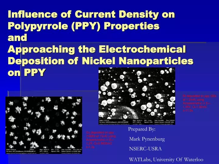
Influence of Current Density on Polypyrrole (PPY) Properties and Approaching the Electrochemical Deposition of Nickel Nanoparticles on PPY. Ni deposited on ppy (20s at 1.2mA) using Amperometric i-t E=-1.25V, Q=1.92mC t=17.5s. Prepared By: Mark Pynenburg NSERC-USRA

E N D
Influence of Current Density on Polypyrrole (PPY) Properties and Approaching the Electrochemical Deposition of Nickel Nanoparticles on PPY Ni deposited on ppy (20s at 1.2mA) using Amperometric i-t E=-1.25V, Q=1.92mC t=17.5s Prepared By: Mark Pynenburg NSERC-USRA WATLabs, University Of Waterloo Cu deposited on ppy (1600s at 15uA) using Amperometric i-t E=-1.2V, Q=0.5635mC t=1.3s
Outline • Experimental Objectives. • Experimental Setup. • Wafer Preparation • Electrochemical Deposition Station. • SEM/AFM Imaging • Current Density. • Motivation • Theoretical • Discussion • Nickel Deposition. • Pulse Electrodeposition (PED) • 2nd Deposition Problem • Conclusions • Moving Forward • Acknowledgements
Experiment Objectives • To explore the effects of current density on ppy film properties. • To prepare monoshaped and monosized nickel nanoparticles on ppy film by electrochemical deposition.
Experimental Setup • Preparation of Au sputtered 2.5mm X 15mm Si Wafer: • Ultrasonic pre-cut wafers in wash acetone. • Rinse wafers with isopropyl alcohol. • Bake wafers @ 80C under vacuum. Purging once with nitrogen after ½ hour then under vacuum again for 1 hour. • Allow wafers to cool in dry box under nitrogen. Etch surface for 30s using magnetron sputter-coater under 150mTorr Ar with 20mA current. Sputter approximately 100nm Au film using sputter: 4 applications of approx. 25nm each done under 50mTorr Ar with 60 to 80mA current for 120s. • Use electrochemical station (potentio/galvanostat) to deposit ppy and metals.
Electrochemical Station Working Electrode Stored in 3M KCl Solution Counter Electrode Reference Electrode Au covered Si wafer A V Computer Display Output Electrochemical Control Module
Electrochemical Station Ppy & metal solutions bubbled with N2 or Ar for at least 20 min prior to deposition Counter Electrode flamed for 30 second before deposition
Current Density Motivation Electrochemical Synthesis of Polypyrrole: Influence of Current Density on Structure, K. West et al., Synthetic Metals 55-57 (1993) 1412-1417 Focused on the deposition of ppy in a non-aqueous environment: 0.5M LiClO4 (electrolyte) in propylene carbonate. Deposited films with current densities between 6.5 uA/cm2 and 3.84 mA/cm2. Identified low current and high current forms. Characterized films with cyclic voltammograms and in situ spectroscopy (320-1200 nm). Authors’ Conclusions Current density crucial parameter in determining properties of ppy. Low current density closer to intrinsic properties of pure ppy. Should be used as a reference for investigating effects of changing conditions on properties. Adding water has little or no influence on properties of this modification but lowers stability. Lower current density incorporates more anions.
Theoretical • Pyrrole dissolved in solvent with anionic doping salt is oxidized at the surface of an electrode by application of an anodic potential. • As s result of initial oxidation, the radical cation formed reacts with other monomers to form oligomeric products and then the polymer. • Conjugation in the polymer lowers its oxidation potential wrt to monomer. Therefore synthesis and anionic doping occur concurrently. • Anion is incorporated into polymer to ensure electrical neutrality of film. • Mechanism is controversial - # of competing schemes • Equation governing thickness of ppy deposition: Q = i x t A = .15 to .1875 cm2 Mppy = 67.09 g/mol F = 96500C/mol n = (2 + .025) p – density (0.967,1.2, 1.5g/cm3?)
PPY Density Determination Using Quasiempirical Method • Used AFM to obtain thickness of films at various points. • Using the values from the slopes of the graph 1.0224x10⁻³ to 7.8876x10⁻⁴ cm/C. Intercept negligible. • Assume value of n as either 2 or 2.25 and range of area was from .15 to .1875 cm2. • Thus able to obtain an upper and lower bound on density ρ = 2.9 to 1.6g/cm3 • Lower number seems more reasonable. Agrees better with literature and previous value. • Formula doesn’t account for the doping anions. • Instead of talking about ppy thickness use galvanostatic current and time of polymerization.
Discussion • In the course of the current deposition work discovered factors that may effect ppy properties: • Purity of the monomer solution. • Age of ppy film when doing subsequent metal deposition.
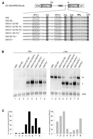
Variations in PPY due to age of pyrrole • Larger variation in ppy depositions before freshly distilling pyrrole • Top old ppy 1600s 15uA dep potential varies by 0.07V • Bottom fresh ppy 2000s 12uA dep potential varies by 0.014V
The effect of PPY age on Cu deposition Cu deposited on ppy using Amperometric i-t E= -1.4V, Q=0.5635mC, t < 1s Top left ppy 20s/1.2mA, Top right 160s/150uA, left 1000s/24uA Red day old ppy film Blue fresh ppy film
Current Density on Cu Deposition • Red 20s 1.2mA • Blue 160s 0.15mA • Brown 500s 48uA • Green 1000s 24uA • Navy 2000s 12uA Cu deposited on ppy using Amperometric i-t E=-1.4V, Q=0.5635mC t <1s
Current Density on Cu Deposition -1.2V Deposition time varied with film type/age ppy 320s @ 75uA ppy 160s @ 150uA ppy 800s @ 30uA ppy 1600s @ 15uA
The trouble with cyclic voltammograms (CVs) • Six identically deposited ppy films gave vastly different results when CVs done in dep. electrolyte 0.1M NaClO4
Nickel • Observed similar results to earlier work of Neha and Sabrina • Both observed ppy 2 step due likely to monomer age which may have effected Ni deposition properties • When Ni deposition has occurred usually very low numbers • Varying pH and potential yielded little new information
Nickel • When ppy is reduced the incorporated perchlorate anions are released according to the reaction: • (PPy+ClO4-) + e- PPy0 + ClO4- • Metals are to be deposited by reduction. • Reduction current has two components, one due to reduction of ppy with simultaneous release of anions as counterions illustrated above, and when a negative enough potential for Ni reduction is applied: • NiSO4+2 + 2e Ni0 + xSO4
Nickel • However picture is much more complicated: • Boric Acid is used as a buffer at electrode surface. • Sulfuric acid is used to acidify medium to supress formation of hydroxides. • Deposited Ni can act as a catalyst for hydrogen evolution, different sites on Ni deposit can favour a variety of adsorbants, mechanism of deposition complicated. • See papers: “Nanocrystalline Copper by Pulsed Electrodeposition”, H. Natter & R. Hempelmann, J. Phys. Chem. 1996, 100, 19525-19532. and “First Stages of Ni Deposition on Vitreous Carbon from Sulfate Solutions”, A. G. Munoz et al., Thin Solid Films, 429 (2003) 119-128.
Pulse Electrodeposition (PED) • Motivation • Nanocrystalline Copper by Pulsed Electrodeposition, H. Natter & R. Hempelmann, J. Phys. Chem. 1996, 100, 19525-19532. • Use shape of current pulses to influence grain size, distribution, shape. • Truncated octahedral Cu formed exhibiting self organizational behaviour • Initial Ni experiments using PED not as promising.
Pulse Electrodeposition (PED) • Short (1 to 10ms) high current/potential pulse followed by long rest (>100ms) • High nucleation rate • Surface of electrode has chance to return to equilibrium • Nature of diffusion controlled growth changed
Ni vs. Cu 2nd Deposition • Ni deposition exhibits behavior not observed in Cu deposits. • Often only the first deposition leads to and Cu close agreement between 1st & 2nd dep. 1st Ni dep. 2nd Ni dep.
Conclusions • Current density: • Has an effect on the nature of ppy film as illustrated by Cu deposition. • Could be due to better ppy conductivity, greater incorporation of anion • Freshly distilled pyrrole improves repeatability. • Due to possible instability of ppy all depositions and CV analysis should be done on the same day. • CV curve performance differences difficult to illustrate due to film instability/CV variations
Conclusions • Nickel: • Something occurs during 1st deposition that effects subsequent Ni deposition • Possible candidates pH, release of perchlorate anions... • Shot gun approach to ideal conditions ineffective in this case.
Moving Forward • To solve the Ni deposition problem by: • Developing a proposal for systematic approach. • Number of variables makes for difficult task (over 10 possible parameters to control) • Make use of EQCM to monitor Ni deposition • Explore parameters that haven’t been considered: • PPY anionic dopant (Cl or SO4), cation-exhange membrane PPY(PSS), current density, NiCl2, PED redux • Perform more CV curve analysis to illustrate structural differences in water do to current density.
Acknowledgements • This work was supported by NSERC-USRA program and Dr. K. T. Leung’s WATLabs group • Presentation template and photographs courtesy of Louis Wong. • Dr. He of CH Instruments for answering any questions I had about the electrodeposition equipment in a timely fashion. • I would like to thank everybody in WATLabs for there help and support.