Download
1 / 1
60 likes | 324 Views
ENERGY IN Radiation. Development, Characterization, and Optimization of a Thermoelectric Generator System Lindsey Bunte , Jonny Hoskins, Tori Johnson, Shane McCauley School of Chemical, Biological and Environmental Engineering Sponsors: Perpetua Power Source Technologies & ONAMI.

E N D
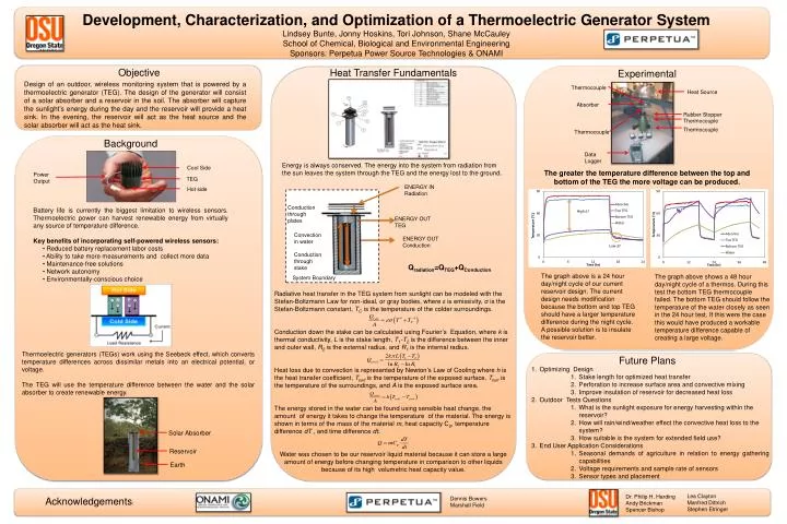
ENERGY IN Radiation Development, Characterization, and Optimization of a Thermoelectric Generator System Lindsey Bunte, Jonny Hoskins, Tori Johnson, Shane McCauley School of Chemical, Biological and Environmental Engineering Sponsors: Perpetua Power Source Technologies & ONAMI Conduction through plates ENERGY OUT TEG Convection in water Conduction through stake ENERGY OUT Conduction Objective Heat Transfer Fundamentals Experimental Design of an outdoor, wireless monitoring system that is powered by a thermoelectric generator (TEG). The design of the generator will consist of a solar absorber and a reservoir in the soil. The absorber will capture the sunlight’s energy during the day and the reservoir will provide a heat sink. In the evening, the reservoir will act as the heat source and the solar absorber will act as the heat sink. Background Energy is always conserved. The energy into the system from radiation from the sun leaves the system through the TEG and the energy lost to the ground. Cool Side The greater the temperature difference between the top and bottom of the TEG the more voltage can be produced. Power Output TEG Hot side Thermocouple Heat Source Battery life is currently the biggest limitation to wireless sensors. Thermoelectric power can harvest renewable energy from virtually any source of temperature difference. Key benefits of incorporating self-powered wireless sensors: • Reduced battery replacement labor costs• Ability to take more measurements and collect more data• Maintenance-free solutions• Network autonomy• Environmentally-conscious choice High ∆T Absorber Rubber Stopper Thermocouple Thermocouple Thermocouple Qradiation=QTEG+QConduction Data Logger The graph above is a 24 hour day/night cycle of our current reservoir design. The current design needs modification because the bottom and top TEG should have a larger temperature difference during the night cycle. A possible solution is to insulate the reservoir better. The graph above shows a 48 hour day/night cycle of a thermos. During this test the bottom TEG thermocouple failed. The bottom TEG should follow the temperature of the water closely as seen in the 24 hour test. If this were the case this would have produced a workable temperature difference capable of creating a large voltage. System Boundary Thermoelectric generators (TEGs) work using the Seebeck effect, which converts temperature differences across dissimilar metals into an electrical potential, or voltage. The TEG will use the temperature difference between the water and the solar absorber to create renewable energy. Future Plans • Optimizing Design • Stake length for optimized heat transfer • Perforation to increase surface area and convective mixing • Improve insulation of reservoir for decreased heat loss • Outdoor Tests Questions • What is the sunlight exposure for energy harvesting within the reservoir? • How will rain/wind/weather effect the convective heat loss to the system? • How suitable is the system for extended field use? • End User Application Considerations • Seasonal demands of agriculture in relation to energy gathering capabilities • Voltage requirements and sample rate of sensors • Sensor types and placement Radiative heat transfer in the TEG system from sunlight can be modeled with the Stefan-Boltzmann Law for non-ideal, or gray bodies, where ε is emissivity, σ is the Stefan-Boltzmann constant, TC is the temperature of the colder surroundings. Conduction down the stake can be calculated using Fourier’s Equation, where k is thermal conductivity, L is the stake length, T1-T2 is the difference between the inner and outer wall, R2 is the external radius, and R1 is the internal radius. Heat loss due to convection is represented by Newton’s Law of Cooling where h is the heat transfer coefficient, Tsurfis the temperature of the exposed surface, Tsurr is the temperature of the surroundings, and A is the exposed surface area. The energy stored in the water can be found using sensible heat change, the amount of energy it takes to change the temperature of the material. The energy is shown in terms of the mass of the material m, heat capacity Cp, temperature difference dT , and time difference dt. Water was chosen to be our reservoir liquid material because it can store a large amount of energy before changing temperature in comparison to other liquids because of its high volumetric heat capacity value. Solar Absorber Lea Clayton Manfred Dittrich Stephen Etringer Dr. Philip H. Harding Andy Brickman Spencer Bishop Acknowledgements: Dennis Bowers Marshall Field Reservoir Earth