Download
1 / 39
390 likes | 523 Views
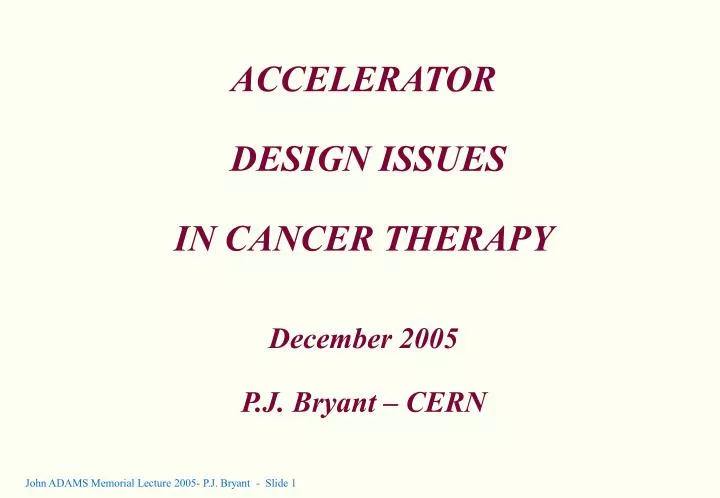
ACCELERATOR DESIGN ISSUES IN CANCER THERAPY December 2005 P.J. Bryant – CERN. Introduction Hadrons & voxel scanning Experimental setup A closer look… Energy deposition How particles kill The magic of carbon Beam delivery systems Assembling the facts Part played by CERN EULIMA

E N D
ACCELERATOR DESIGN ISSUES IN CANCER THERAPYDecember 2005P.J. Bryant – CERN
Introduction Hadrons & voxel scanning Experimental setup A closer look… Energy deposition How particles kill The magic of carbon Beam delivery systems Assembling the facts Part played by CERN EULIMA PIMMS International agreements ENLIGHT PIMMS design Configuring the resonance Smoothing the spill Beam size control ‘Riesenrad’ gantry Conclusion Contents
Hadron therapy by voxel scanning In 1946, Bob Wilson publishes “Radiobiological use of fast protons”. He writes about the Bragg peak behaviour and he has the astute foresight to mention the possible use of carbon ions.
Some questions… • Hadron therapy by voxel scanning is a high-technology marvel, but what happens if the tumour moves or changes shape, e.g. a lung cancer? • What is so special about carbon? • The world has traditionally relied on electron and photon therapies and still relies on photon therapies. Why are photons (X-rays) so successful? • A brief internet search reveals a wide range of treatments. How does one tell the better from the good? • Let’s take a closer look.
Bragg peak behaviour • Single Bragg peak for protons By superimposing several peaks of successively lower energies the Spread-Out Bragg Peak is formed (SOBP). • Single Bragg peaks for carbon ions These peaks are too narrow to be useful for a SOBP and have to be widened with a ridge filter.
Comparison of dose profiles with a single entry port [Electrons resemble photons except the peak is shallower and the decay is more rapid.]
Effect of rotating about an axis in the tumour • Rotation around an axis in the tumour improves the local photon distribution and the same action will improve the proton and ion distributions even more. • This is why photon treatments have 8 or 9 entry ports while proton treatments have only 2 or 3.
Universitätsklinik für Strahlentherapie und Strahlenbiologie, AKH, Wien Comparison of Treatment Plans Glandula parotid cancer (Ohrspeicheldrüsenkarzinom) Photons 5 fields Protons 3 fields Photons 2 fields
Photons & protons (low LET) 'Therapy' particles Kill mainly by forming active radicals such as OH* that poison the cell chemically. Damage by active radicals occurs in the normal environment. During millions of years of evolution, living tissue has learnt to repair this damage, except that cancer cells do so less readily. The separation of the survival curves for healthy and cancerous cells opens a ‘window’ on a ‘therapy treatment’, rather than a ‘radio-surgery treatment’. How particles kill – part I
Treatment The treatment is applied in 20 to 30, consecutive daily sessions. The majority of the healthy cells repair, but the cancer cells progressively die. The treatment is calculated to leave of 1 in 109 chance for a cancer cell to survive. Tolerance The success of photon treatment, even with older and relatively imprecise machines, may be partly due to the 'tolerance' of therapy particles. Since healthy cells are calculated to survive, the 'leakage' of medium level doses into surrounding tissue is less of an issue. On the other hand, long-term complications appear to be related to the total dose and unnecessary irradiation must always be avoided. ‘Therapy’ particles
Light ions (high LET) 'Surgery' particles Kill mainly by creating a high density of secondary electrons by ionisation. These electrons make DNA double-strand breaks that are hard to repair. Double-strand breaks are not part of the normal environment and both normal and cancer cells can rarely repair and suicide themselves. Double strand breaks are caused by secondary electrons. With protons the electron density is low and most cells escape this damage. For carbon ions a DNA molecule has little chance to escape whether it is healthy or not. How particles kill – part II
RBE of light ions ‘Overkill region’ ‘Surgery region’ ‘Therapy region’
Photon and electron beam delivery • Collimator for transverse shape. • Use of several entry ports.
Proton passive beam spreading delivery (full volume) • Bragg peak to tailor distal edge. • Collimator for transverse shape. • Use of 2 or 3 entry ports. Bolus: Low Z material (plexiglass) for energy loss not scattering. Has to be machined for each case.
Proton passive beam spreading • Bragg peak to tailor distal edge. • Collimator adapted to transverse shape of each slice. • 1, or perhaps 2 entry ports.
Double-scatterer system for protons • First scatterer significantly increases angular divergence. • Second scatterer is shaped to scatter the dense centre to the edges while letting the edges pass largely unaffected. • ~60% of the beam will belost. • Scatterers will be a high Z material to favour scattering (copper). Double scatterer Collimator Quasi-uniform beam (within 2%) over 20 20 cm2
Proton beam preparation before the scatterers • Adjust the beam energy (Bragg-peak) to the maximum tumour depth. • Stepwise energy modulation to define the slices in the tumour. • Fast modulation by a rotating propeller to create SOBP. • Static modulation by a ‘ridge’ filter may be used to replace propeller. • Low-Z materials preferred for less scattering (plexiglass).
Wobbling of an enlarged beam spot • Passive spreading of ions beams is not recommended because the beam fragments and the impurities have different penetrations and radio-biological effectiveness (RBE). • In the above, the scatterer/absorber produces an enlarged beam transversely with a momentum spread, typically 2 cm 2 cm 1 cm (penetration spread). • The enlarged spot (‘blob’) is rapidly ‘wobbled’ in a circular motion across the collimator to give a uniform irradiation field.
Optical spreading by folding phase space • Normal beam ellipse • Stretch ellipse to large amplitudes • Introduce a faster phase advance for large amplitudes with octupoles and project beam onto real axis.
Active voxel scanning • Highest precision,but the small beam size makes tumour movement a serious limitation. • Well suited to light ions that scatter less and therefore preserve the small beam sizes. • Synchrotrons offer best flexibility. • From full-volume passive spreading through to voxel scanning, there has been a reduction in the elementary volumes that are irradiated and a corresponding increase of about 3 orders of magnitude in the speed required from the on-line dosimetry system to maintain the treatment time and accuracy. This makes voxel scanning the highest technology variant.
The part played by CERN • EULIMA, Nov. 1988, Aug 1990 + Final Report date ? Most of the basic ideas are mentioned. • CERN hosted the PIMMS (Proton Ion Medical Machine Study) 1996-2000. Several advances in the optics and a detailed design. • CERN has collaboration agreements with most of the European hadron therapy projects. • ENLIGHT Workshop provides a forum for the European hadron therapy projects.
PIMMS • The main aim for the synchrotron ring was to stabilise the slow beam spill. The slow extraction is needed to give time for the dosimetry. However, if the spill is unstable the dosimetry is more difficult and the treatment time has to be extended. • The main achievement for the transfer lines was a beam size control that used the concept of an unfilled ellipse and the ‘bar of charge’ and a modular design. • The main development for the beam delivery was the ‘Riesenrad’ gantry and its optical rotator. • PIMMS was a demonstration machine, a ‘pedagogic’ solution. National projects were left to remove unwanted features, compress the optics etc.
Extraction configuration (‘Steinbach’ diagrams) • ‘Quadrupole-driven’ Optical parameters, bumps, orbits etc. are changing. Beam is extracted from large to small amplitudes and spill changes its sensitivity to ripple with amplitude. Not recommended. • ‘Acceleration-driven’ Machine optics are rigorously constant. Characteristics of beam entering resonance are constant. Hardt condition, intrinsic smoothing,betatron core and front-end acceleration can operate. PIMMS solution. • ‘RF excitation-driven’ Has advantage of a fast switching time. A form of the Hardt condition can be applied. No front-end acceleration into the resonance.
Stable region Electrostatic septum Unstable region Centre of chamber Slow extraction Extracted segment of the separatrix. • In a linear lattice, the beam follows ellipses in phase space. • Under the influence of a sextupole and with a tune value near 1/3 or 2/3 the ellipses are distorted. • As larger and larger betatron amplitudes are considered the ellipses progressively change into triangles. • Finally there is a ‘last stable triangle’ and the particles come to a bifurcation of phase space and they dive out of the machine along the separatrices.
Sensitivity of slow extractions is legendary • This leads to extremely tight ripple tolerances for power converters. • Slow extraction can be likened to the shaving action on a wood-turning lathe. • The width of the wood is the energy spread. • The thickness of the shaving is the horizontal emittance of the extracted beam. • For ~1’000’000 turns, the shaving is extremely thin and, clearly, this is a very delicate process. • The slightest vibration can cause the chisel to jump and chop the shaving.
Configuring the extraction • The previous slide, showed the analogy of thequadrupole-driven extraction. • Theacceleration-driven extractionis shown below. • This method mixes all betatron amplitudes, which gives a smoothing effect for ripple. • The width of the shaving (i.e. the extracted energy spread) is now smaller than the width of the wood (i.e. the original beam). • The angle of the cut is analogous to theHardt Condition, which minimises the losses at the extraction septum.
Intrinsic smoothing • Elementary ‘strip spill’ This occurs in a quadrupole-driven extraction. ~50% leave in a spike from the corner and ~50% leave from the side, more or less evenly over the spill. • ‘Band spill’ As occurs in the acceleration-driven extraction of PIMMS. Spikes are spread out, lowering the high frequency (kHz) component.
De-sensitising the spill • The idea is to increase the velocity of the beam as it enters the resonance, so that it is well above the velocity caused by the ripple. • The top picture shows the ‘beam’ advancing at the speed of the betatron core and being dominated by the ripple. • In the lower picture, the ‘beam’ speeds up just before the resonance so that the ripple becomes less influential. • This is called ‘front-end’ acceleration and can be done by an empty rf bucket or by rf noise.
Empty bucket chanelling • The betatron core slowly accelerates the beam into the resonance (upwards in the diagram). • The empty rf buckets are nearly stationary. If they were to be filled, they would accelerate their beam in the opposite sense to the betatron core. • When the slowly moving beam meets the empty buckets, it has to stream round the buckets through a narrow phase-space gap at a much higher speed to maintain the flow. • The beam enters the resonance and is extracted.
Beam size control • The extracted segment (in blue) is called the ‘bar of charge’. • The bar of charge is about 10 mm long and has a very small angular spread. • Fitting an ellipse to this narrow bar is impractical. • Instead the bar is regarded as a diameter of a larger unfilled ellipse. • The bar turns at the rate of the phase advance. • A phase shifter can be used to turn the bar and change the projected beam size.
Gantries • Conical gantries: Ideal for passive spreading of protons. The IBA gantry shown is ~110 t and is commercially available. The bends are 45º and 135º. All scanning or spreading is done in nozzle after the last bend. • Cylindrical gantries: This design is ideal for parallel scanning for voxel treatments. GSI is building an ion version ~700 t and XX MW. [Note that iso-centric gantries have limited room at the iso-centre and the large support rings are especially vulnerable and expensive.] • PIMMS ‘Riesenrad’exo-centric gantryfor ions. • Patient in a “false” room, which is basically unlimited in size. • Keep the heavy magnet (~70 t) close to the axis. • Only 90° of bending.
Matching to Gantries – part I • For medical applications any dependency of beam size or distribution on gantry angle must be avoided. • Suitable for cyclotron beams: • Use symmetric beam, identical particle distributions and identical optical functions at rotation point.
Matching to Gantries – part II • Maps the beam 1:1 to the gantry independent of the angle. • This is the rotator solution and it maps the dispersion function and the Twiss functions rigorously to the gantry coordinate system.
Conclusions • Photons (X-rays) are a tough act to beat with a very long and successful history (see Röntgen first X-ray January 23rd 1896). • Since Bob Wilson’s paper in 1946, it was clear that protons offered better conformity of the dose to the tumour shape, but little happened on the commercial front except for Loma Linda that was FNAL-driven. • Carbon ions offer even better precision and a harder ‘hit’ against radio-resistant tumours, but it is too early to say that the battle is won on this front. • Times may now be changing for proton centres with the commercial success of IBA, Belgium. • Sensing the hadron competition the photon machine manufacturers have upgraded their machines to the newer IMRT models. • The Austrian Government has decreed that hadron therapy shall be reimbursed by medical insurance to the same level as photon treatments. • The advantages of the ‘Riesenrad’ gantry are still not widely accepted.