Download
1 / 119
1.23k likes | 1.26k Views
Hydraulic Pump. Presented by Prof. N V Avhad. Content. Types of pump Classification Principle of working and constructional details of Vane pumps Gear pumps Radial and axial plunger pumps Screw pumps Power and efficiency calculations Characteristics curves

E N D
Hydraulic Pump Presented by Prof. N V Avhad
Content • Types of pump • Classification • Principle of working and constructional details of • Vane pumps • Gear pumps • Radial and axial plunger pumps • Screw pumps • Power and efficiency calculations • Characteristics curves • Selection of pumps for hydraulic power trans.
Introduction • Converts Mechanical to Hydraulic energy • Used to generates the force necessary to move the load • How the pump works?
ClassificationofPump 1. Classification based on displacement: • Non-positive displacement (hydrodynamic pumps) • Positive displacement (hydrostatic pumps) 2. Classification based on delivery: • Constant delivery pumps • Variable delivery pumps 3. Classification based on motion: • Rotary pump • Reciprocating pump
Classification based on Displacement • Positive displacement pumps Flow rate does not change with head • In pump volume changes from max. to min. • Deliver a constant volume of fluid • Discharge quantity per revolution is fixed • Produce fluid flow proportional to their displacement and rotor speed • High-pressure and low-pressure areas (means input and output region) are separated and hence the fluid cannot leak back due to higher pressure at the outlets • Most suited and universally accepted for hydraulic systems. • Fluid flow rate of these pumps ranges from 0.1 to 15,000 gpm, • Pressure head ranges between 10 to 100,000 psi
B. Non-positive displacement pumps Hydro-dynamic pumps flow rate decreases with head • Not withstanding high pressures and used for low-pressure and high-volume flow applications. • Fluid pressure and flow generated due to inertia effect of the fluid. • Fluid motion is generated due to rotating propeller. • Create pressure up to 40 bar and high volume system.
Advantages of positive displacement pumps over non-positive displacement pumps • Operate at very high pressures of up to 800 bar • High volumetric efficiency of up to 98%. • Highly efficient and almost constant throughout the designed pressure range. • Compact unit and high power-to-weight ratio. • Obtain a smooth and precisely controlled motion. • Produce only the amount of flow required to move the load at the desired velocity. • Great flexibility of performance. • Operate over a wide range of pressures and speeds.
Advantages of Non Disp. Pump 1.Non-displacement pumps have fewer moving parts. 2.Initial and maintenance cost is low. 3. They give smooth continuous flow. 4. They are suitable for handling almost all types of fluids including slurries and sledges. 5.Their operation is simple and reliable. Disadvantages Non Disp. Pump 1.Non-displacement pumps are not self-priming and hence they must be positioned below the fluid level. 2. Discharge is a function of output resistance. 3.Low volumetric efficiency.
Classification Based on Delivery Constant Delivery Pumps • Always deliver the same quantity of fluid in a given time at the operating speed and temperature. • Used with relatively simple machines, such as saws or drill presses or where a group of machines is operated with no specific relationship among their relative speeds. • Power for reciprocating actuators is most often provided by constant volume pumps. Variable Delivery Pumps • The output of variable volume pumps may be varied either manually or automatically with no change in the input speed to the pump. • Variable volume pumps are frequently used for rewinds, constant tension devices or where a group of separate drives has an integrated speed relationship such as a conveyor system or continuous processing equipment.
Pumping Theory • Used for converting mechanical energy into hydraulic energy. • Driven by a prime mover such as an electric motor. • It basically performs two functions. • It creates a partial vacuum at the pump inlet port. This vacuum enables atmospheric pressure to force the fluid from the reservoir into the pump. • The mechanical action of the pump traps this fluid within the pumping cavities, transports it through the pump and forces it into the hydraulic system. • Pressure is created by the resistance to flow. • All pumps operate by creating a partial vacuum at the intake, and a mechanical force at the outlet that induces flow.
1. As the piston moves to the left, a partial vacuum is created in the pump chamber that holds the outlet valve in place against its seat and induces flow from the reservoir that is at a higher (atmospheric) pressure. As this flow is produced, the inlet valve is temporarily displaced by the force of fluid, permitting the flow into the pump chamber (suction stroke). 2. When the piston moves to the right, the resistance at the valves causes an immediate increase in the pressure that forces the inlet valve against its seat and opens the outlet valve thereby permitting the fluid to flow into the system. If the outlet port opens directly to the atmosphere, the only pressure developed is the one required to open the outlet valve(delivery stroke).
Classification Based on Motion • 1. Type of motion of pumping element: • Rotary pumps, for example, gear pumps and vane pumps. • Reciprocating pumps, for example, piston pumps. • 2. Displacement characteristics: • Fixed displacement pumps. • Variable displacement pumps.
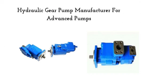
Gear Pumps • It has two meshed gears revolving about their respective axes. • These gears are the only moving parts in the pump. • These pump includes helical and herringbone gear sets (instead of spur gears), lobe shaped rotors similar to Roots blowers, and mechanical designs that allow the stacking of pumps. Based upon the design, the gear pumps are classified as: • External gear pumps • Lobe pumps • Internal gear pumps • Gerotor pumps
Gear pumps are used to pump • Petrochemicals: Pure or filled bitumen, pitch, diesel oil, crude oil, lube oil etc. • Chemicals: Sodium silicate, acids, plastics, mixed chemicals, isocyanates etc. • Paint and ink • Resins and adhesives • Pulp and paper: acid, soap, lye, black liquor, kaolin, lime, latex, sludge etc. • Food: Chocolate, cacao butter, fillers, sugar, vegetable fats and oils, molasses, animal food etc.
Gear Pumps • Less expensive but limited to pressures below 140 bar. • Noisy in operation than either vane or piston pumps. • Fixed displacement type of pump, which means that the amount of fluid displaced for each revolution of the drive shaft is theoretically constant.
External Gear Pumps • Used in low-pressure ranges due to their long operating life, high efficiency and low cost. • It consist of a pump housing in which a pair of precisely machined meshing gears runs with minimal radial and axial clearance. • One of the gears, called a driver and is driven by a prime mover. • As the teeth of the two gears separate, the fluid from the pump inlet gets trapped between the rotating gear cavities and pump housing. • The trapped fluid is then carried around the periphery of the pump casing and delivered to outlet port. • The teeth of precisely meshed gears provide almost a perfect seal between the pump inlet and the pump outlet. • Inlet is at the point of separation and the outlet at the point of mesh.
Internal Gear Pumps They consist of two gears: An external gear and an internal gear. The crescent placed in between these acts as a seal between the suction and discharge. When a pump operates, the external gear drives the internal gear and both gears rotate in the same direction. The fluid fills the cavities formed by the rotating teeth and the stationary crescent. Both the gears transport the fluid through the pump. The crescent seals the low-pressure pump inlet from the high-pressure pump outlet. These pumps have a higher pressure capability than external gear pumps.
Applications Internal Gear Pump • All varieties of fuel oil • Resins and Polymers • Alcohols and solvents • Asphalt, Bitumen, and Tar • Polyurethane foam • Food products such as corn syrup, chocolate, and peanut butter • Paint, inks, and pigments • Soaps and surfactants • Glycol
Lobe Pumps • Operation is similar to that of external gear pump, but they generally have a higher volumetric capacity per revolution. • The output may be slightly greater pulsation because of the smaller number of meshing elements. • Lobe pumps, unlike external gear pumps, have both elements externally driven and neither element has any contact with the other. • Quite in operation. • Lobe contact is prevented by external timing gears located in the gearbox. • Pump shaft support bearings are located in the gearbox, and because the bearings are out of the pumped liquid, pressure is limited by bearing location and shaft deflection. • They do not lose efficiency with use. • They are similar to external gear pumps with respect to the feature of reversibility.
Features & Benefits • Higher Pressure Capabilities For long distance transfer of high viscosity liquids. • Easy Timing Rotors and gears are positively located on key shafts. • Simple End Clearance Adjustment Compared to other lobe pumps which require shimming. • Shaft Seal Options Including packed gland, component seal and cartridge seal options. • Excellent NPSHr Fluid access on three sides of rotors enhances filling with highly viscous fluids and minimizes pulsation. • Run Dry Continuously Non-contacting rotors enable continuous run-dry with flushed seal, minimizing chance of failure due to operator error. Performance • Max. Capacity: to 820 GPM (186 M3/Hr) • Max. Pressure: to 400 PSI (27 BAR) • Viscosity Range: 28 to 2,000,000 SSU (Saybolt universal second) • Temperature Range: -40°F to +400°F (-40°C to +205°C)
Stages of operation of Lobe pump 1.As the lobes come out of mesh, they create expanding volume on the inlet side of the pump. Liquid flows into the cavity and is trapped by the lobes as they rotate. 2.Liquid travels around the interior of the casing in pockets between the lobes and the casing (it does not pass between the lobes). 3.Finally, the meshing of the lobes forces the liquid through the outlet port under pressure.
Advantages 1. Lobe pumps can handle solids, slurries, pastes and many liquid. 2. No metal-to-metal contact. 3. Superior CIP(Cleaning in Place) /SIP(Sterilization in Place) capabilities. 4. Long-term dry run (with lubrication to seals). 5. Non-pulsating discharge. Disadvantages 1. Require timing gears. 2. Require two seals. 3. Reduced lift with thin liquids. Applications 1. Polymers. 2. Paper coatings. 3. Soaps and surfactants. 4. Paints and dyes. 5. Rubber and adhesives. 6. Pharmaceuticals. 7. Food applications.
Gerotor Pumps • Inner gear rotor is called a gerotor element. • The gerotor element is driven by a prime mover and during the operation drives outer gear rotor around as they mesh together. • The gerotor has one tooth less than the outer internal idler gear. • Each tooth of the gerotor is always in sliding contact with the surface of the outer element. • The teeth of the two elements engage at just one place to seal the pumping chambers from each other. • The pockets of increasing size are suction pockets and those of decreasing size are discharge pockets. • where b is the tooth height, Z is the number of rotor teeth, Amax is the maximum area between male and female gears (unmeshed – occurs at inlet) and Amin is the minimum area between male and female gears (meshed – occurs at outlet).
Applications of Gerotor Pump • Light fuel oils • Lube oil • Cooking oils • Hydraulic fluid
Screw Pumps • These pumps have two or more gear-driven helical meshing screws in a close fitting case to develop the desired pressure. • These screws mesh to form a fluid-type seal between the screws and casing. • A two-screw pump consists of two parallel rotors with inter-meshing threads rotating in a closely machined casing. • The driving screw and driven screw are connected by means of timing gears. • When the screws turn, the space between the threads is divided into compartments. • As the screws rotate, the inlet side of the pump is flooded with hydraulic fluid because of partial vacuum. • When the screws turn in normal rotation, the fluid contained in these compartments is pushed uniformly along the axis toward the center of the pump, where the compartments discharge the fluid. • Here the fluid does not rotate but moves linearly as a nut on threads. • There is no pulsation and very quiet operating.
Screw pump Advantages 1.They are self-priming and more reliable. 2. They are quiet due to rolling action of screw spindles. 3.They can handle liquids containing gases and vapor. 4. They have long service life. Disadvantages 1.They are bulky and heavy. 2.They are sensitive to viscosity changes of the fluid. 3. They have low volumetric and mechanical efficiencies. 4. Manufacturing cost of precision screw is high.
Vane pumps Fixed Displacement Vane pump Variable Displacement Vane pump Balanced Vane pump Unbalanced Vane pump
Types of Vane • Dual Vane -Two vanes in each slot • Intra Vane -Smaller vane within larger vane • Pin Vane -Pressure is directed underside the pin • Spring Loaded Vane -force vane against cam ring • Angled Vane -Reduce loading on vane
Advantages 1. Vane pumps are self-priming, robust and supply constant delivery at a given speed. 2. They provide uniform discharge with negligible pulsations. 3. Their vanes are self-compensating for wear and vanes can be replaced easily. 4. These pumps do not require check valves. 5. They are light in weight and compact. 6. They can handle liquids containing vapors and gases. 7. Volumetric and overall efficiencies are high. 8. Discharge is less sensitive to changes in viscosity and pressure variations.