Download
1 / 14
140 likes | 254 Views
The Processor. Andreas Klappenecker CPSC321 Computer Architecture. The Processor: Datapath and Control. We want to implement portions of MIPS memory-reference instructions : lw, sw arithmetic-logical instructions : add, sub, and, or, slt control flow instructions : beq, j

E N D
The Processor Andreas Klappenecker CPSC321 Computer Architecture
The Processor: Datapath and Control We want to implement portions of MIPS • memory-reference instructions: lw, sw • arithmetic-logical instructions: add, sub, and, or, slt • control flow instructions: beq, j We ignore multiply, divide, and other integer and floating point instructions.
Goals • Explain main design principles of • datapath • control • Simplicity • Short exposition of Verilog
Implementation of Instructions • Fetch instruction • Send the PC to the memory location containing the next instruction • Read registers • fetch registers using fields of the instruction • lw needs just one register • most other instructions need two registers • Next steps depend on instruction class
Implementation of Instructions II • Once register operands have been fetched, they can be operated on • to compute a memory address (lw and sw) • to compute an arithmetic result (int ops) • to compare (for a branch) • Use output of the ALU
Implementations of Instructions III • Output of ALU is • written to a register in the case of arithmetic-logical instructions • used as an address in the case of load and store instructions • to determine the next instruction address in the case of branch instructions
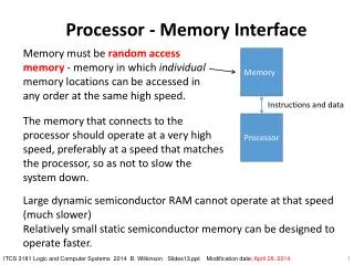
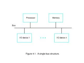
More Implementation Details • Abstract, simplified view • Two types of functional units: • elements that operate on data values (combinational) • elements that contain state (sequential)
Combinatorial and Sequential Elements • The ALU is a combinatorial element • Other elements of the design are not combinatorial, but contain a state • An element with some internal storage is called a state element • State elements have at least two inputs: • data • clock (determines when data is written)
falling edge cycle time rising edge Clocking Methodology • We need to decide when signals can be read and written • We need to specify timing behavior • For simplicity, we assume an edge-triggered clocking strategy (synchronous design) • All storage elements are updated on either raising edge or falling edge:
Synchronous Design • Typical execution: • read contents of some state elements, • send values through some combinational logic • write results to one or more state elements
Refresh you memory! • Read Appendix B about Logic Design • Keywords • latch • D-flip flop • gates • clock • …
D-latch • Two inputs: • the data value to be stored (D) • the clock signal (C) indicating when to read & store D • Two outputs: • the value of the internal state (Q) and it's complement
D flip-flop Output changes only on falling clock edge
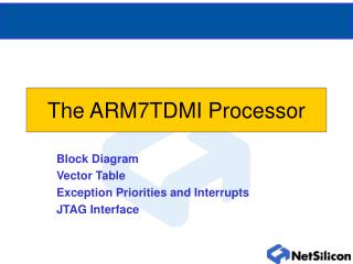
Conclusions • We will use D-flip flops to build the register file • We gradually build up the datapath • Simple components will allow us to do this • We add the control logic a little later • You will need a firm understanding of logic design • Study Chapter 4, read Appendix B