Download
1 / 35
360 likes | 520 Views
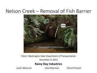
Nelson Creek – Removal of Fish Barrier. Client: Washington State Department of Transportation December 4, 2013 Rainy Day Industries Justin Monsrud Clay Peterman Cheryl Preston. Location Map for Nelson Creek.

E N D
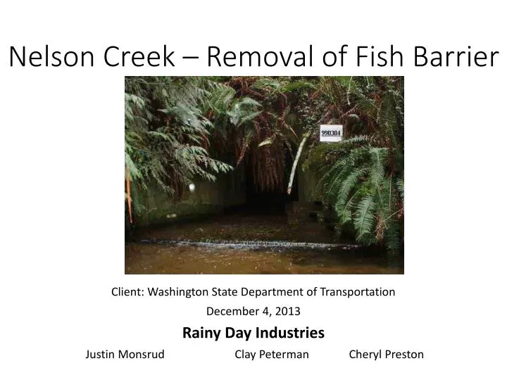
Nelson Creek – Removal of Fish Barrier Client: Washington State Department of Transportation December 4, 2013 Rainy Day Industries Justin Monsrud Clay Peterman Cheryl Preston
Location Map for Nelson Creek This project is located in Clallam County, Wa on SR-112 mile post 47.1 at the crossing of Nelson Creek. The site is location in the Olympic Region west of Port Angeles
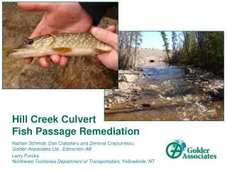
Project Description • Removal of existing box culvert • Construction of a 16’ wide by 10’ high culvert • Precast 3-sided culvert with wing walls. • Strip footing foundations • 130’ long structural earth wall on South side • Reconstruct existing embankments to a slope of 2H:1V • New pavement for roadway • Approximately 175’
Project Justification • The restoration of declining salmon and trout populations • Inability to utilize spawning grounds • Opening passage to natural habitat • Coho Salmon and Steelhead • sea run and resident Cutthroat Trout
Project Scope • develop a traffic re-routing plan • Pavement design of new roadway • Existing impervious surface 17780 approx. 740 ft. • New impervious surface 4200 approx. 175 ft. • Embankment improvements • Earth wall and erosion control design • Removal of existing culvert • Design of new culvert, wing walls, foundation and strip footings.
The Team • Roles and Responsibilities: • Culvert and strip footing designs. • Primary: Justin Monsrud • Secondary: Clay Peterman • Structural earth wall and embankments. • Primary: Clay Peterman • Secondary: Cheryl Preston • Traffic routing and control and pavement design. • Primary: Cheryl Preston • Secondary: Justin Monsrud
Permits and Approval • Local permits for approval: • Clearing, grading, and building permit • Critical area ordinance • Noise variance • State permits for approval: • Aquatic lands permit • Hydraulic Project Approval (HPA) • Federal permits for approval: • CWA Section 401 • CWA Section 402 • Endangered Species Section 7
Temporary Traffic Management Plan • Decision Matrix • Scale 1-10 • 10 most desirable
Temporary Traffic Management Plan • Construction schedule
Soil Borrow • Decision Matrix: • Gravel borrow chosen. • Less sensitivity to moisture.
Culvert Design • Culvert sidewalls are loaded axially and laterally. Have to consider ΦPn and ΦMn. Have to develop a interaction diagram and also consider the limit of cracking at service state.
Culvert Design Channel restoration • Culvert bed material will consist of well graded stream bed sediment (Standard spec 9-03.11.1), stream bed cobbles (Standard spec 9-03.11.2), and stream bed boulders (Standard sec 9-03-.11.3)
Culvert Design • For Precast Culvert installation we will need 14 units total to achieve 106 LF (14 joints adding 3.25” in length)
Structural Earth Wall • South side of project. • Approximately 130 feet long. • No more than 20 feet exposed height. • A 4 foot bench before slope.
Structural Earth Wall • Decision matrix for SE Wall selection. • Chose a gabion retaining wall.
Structural Earth Wall Gabions Concrete Cantilever Sheet Piling
Structural Earth Wall • Design: • 138 feet in length. • 18 feet tall at highest point. • Checks for overturning, sliding, and bearing capacity.
Grading • Requirements: • A 2H:1V slope. • Vegetation to be planted for erosion control
Erosion Control • Vegetation: • Will be from native plants chosen based on effectiveness. • Other: • Wattles, compost socks, and and erosion control blankets will be considered.
Pavement Design • Decision Matrix • Scale 1-10 • 10 most desirable
Pavement Design • Average Daily Traffic (ADT): • 951 units, 26.5% truck traffic • Equivalent Single Axle Load (ESAL): • Design year =201,081. total design=27,418,510 • 15 year performance grade binder: • PG64-16 http://www.pavementinteractive.org/wsdot-esal-application/ LTPPBIND Software
Pavement Design Section 3 WADOT’s Pavement Policy Section 5.2 WSDOT’s Pavement Policy Minimum shoulder requirements Section 5.2.5 WSDOT’s Pavement Policy
Traffic Barrier Design • Decision Matrix • Scale 1-10 • 10 most desirable
Traffic Barrier Design • Beam guardrail type 31 allows 28-31 inch rail height tolerance – Section 1610.06(1) • Terminal ET-31 (TL3) or SKT-SP-MGS (TL3) – Section 1610.06(5)(a) • Anchor Type 10 – Section 1610.06(5)(e) • Steel guardrail posts – Section 1610.06(3) • Guardrail placement case 2-31 for two-way traffic – Section 1610.06(7)
Temporary Traffic Management Plan • Off-site detour
Traffic Barrier Design • Guardrail type 31 placement type 2-31
Traffic Barrier Design • Guardrail anchor type 10
Traffic Barrier Design • Guardrail terminal ET-31 (TL3) or SKT-SP-MGS (TL3)