Download

1 / 19
190 likes | 259 Views
Computer Organization & Assembly Language. CPU executes the program from memory, processing each instruction in turn. it is necessary for the CPU to understand what the instruction is telling it to do.

E N D
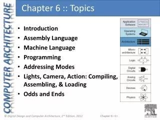
CPU executes the program from memory, processing each instruction in turn. • it is necessary for the CPU to understand what the instruction is telling it to do. • The instructions that can be recognized by a processor are referred to as an 'instruction set‘. • Once the instruction has been recognized, and the actions that should be carried out are decided upon, the actions are then performed before the CPU proceeds on to the next instruction in memory. This process is called the 'instruction execution cycle',
The instruction set is a collection of pre-defined machine codes, which the CPU is designed to expect and be able to act upon when detected. • Different processors have different instruction sets, • to allow for greater features, • easier coding, • and to cope with changes in the actual architecture of the processor itself.
Each machine code of an instruction set consists of two seperate fields: • The opcode is a short code which indicates what operation is expected to be performed. Each operation has a unique opcode. • The operand, or operands, indicate where the data required for the operation can be found and how it can be accessed. • The length of a machine code can vary - common lengths vary from one to twelve bytes in size Opcode Operands
The exact format of the machine codes is again CPU dependant. We presume we are using a 24-bit CPU. This means that the minimum length of the machine codes used here should be 24 binary bits, which in this instance are split as shown in the table below:
Decoding the current instruction, is done by passing the opcode through a decoder (Fig.) • The decoder outputs are connected to the various execution circuits of the control unit and each output • activates “its” execution circuit to execute an instruction. • An execution circuit executes an instruction by • generating a sequence of control signals that are sent to various parts of the computer. • It should also be mentioned that in modern computers, opcodes have different lengths, so the control unit has to figure out the length of the opcode before it can decode it.
The opcode decoder is also the point where invalid opcodes are detected. Most computers have several unused opcodes (to be used in future versions of the machine), • and as a result, some of the decoder outputs do not go to any execution units. Those outputs are connected together and, when any of them becomes active, that signal is used to generate an interrupt.
Instruction execution, however, is different from fetching and decoding and is much more complex than other operations of the control unit cycle. • Modern computers can have a large instruction set with as many as 200–300 instructions. Some instructions are similar and are executed in very similar ways.
Addressing Modes • Immediate • direct • Indirect
Interrupts • Definition: Interrupts are the way the computer responds to urgent or unusual conditions. • Examples of such conditions are: • 1. Invalid opcode. When the control unit decodes the current instruction, it may find that the opcode is invalid (i.e., unused). On many computers, not all opcodes are used. Some opcodes do not correspond to any instruction and are considered invalid. When the control unit identifies such an opcode, it generates an interrupt, since this is both an unusual and an urgent condition. • It has to be handled immediately and the program cannot continue as usual. • 2. Zero-divide. When the ALU starts executing a “divide” instruction, it first tests the divisor. If the • divisor is zero, the ALU generates an interrupt since this is an urgent condition; the division cannot take • place.
Contd. • 3. Timer. On many computers, there is a timer that can be set, by software, to any time interval. When execution time reaches this interval, the timer senses it and generates an interrupt. • 4. Software interrupt. When the program wants to communicate with the operating system, it can artificially generate an interrupt. This interrupt is called a break, a software interrupt, or a supervisor call. It is an important feature of the computer and is discussed later in this section. • 5. Many hardware problems, such as a parity error (in memory or during I/O) or a drop in the voltage can cause interrupts, if the computer is equipped with the appropriate sensors to sense those conditions and to respond accordingly. • 6. I/O interrupts. Those are generated by an I/O device or by the I/O processor. Such an interrupt • indicates that an I/O process has completed or that an I/O problem has been detected.
Introduction to Assembly Language • An instruction is a symbolic representation of a single machine instruction • Consists of: • label always optional • mnemonic always required • operand(s) required by some instructions • comment always optional • Examples: start: mov ax,20 ; initialize the AX register inc bx ; increment the BX register stc ; set the Carry flag
Running DEBUG.EXE, Assembling a Program C:\>debug -A 100 0AFE:0100 mov ax,5 0AFE:0103 add ax,10 0AFE:0106 add ax,20 0AFE:0109 mov [120],ax 0AFE:010C int 20 0AFE:010E assemble, starting at offset 100 Press ENTER to return to command mode
Tracing the Sample Program. • -T • AX=0005 BX=0000 CX=0000 DX=0000 SP=FFEE BP=0000 SI=0000 DI=0000 • DS=0AFE ES=0AFE SS=0AFE CS=0AFE IP=0103 NV UP EI PL NZ NA PO NC • 0AFE:0103 051000 ADD AX,0010 • -T • AX=0015 BX=0000 CX=0000 DX=0000 SP=FFEE BP=0000 SI=0000 DI=0000 • DS=0AFE ES=0AFE SS=0AFE CS=0AFE IP=0106 NV UP EI PL NZ NA PO NC • 0AFE:0106 052000 ADD AX,0020 • -T • AX=0035 BX=0000 CX=0000 DX=0000 SP=FFEE BP=0000 SI=0000 DI=0000 • DS=0AFE ES=0AFE SS=0AFE CS=0AFE IP=0109 NV UP EI PL NZ NA PE NC • 0AFE:0109 A32001 MOV [0120],AX
MOV [0120],AX -D 120,121 0AFE:0120 35 00 AX=0035 BX=0000 CX=0000 DX=0000 SP=FFEE BP=0000 SI=0000 DI=0000 DS=0AFE ES=0AFE SS=0AFE CS=0AFE IP=010C NV UP EI PL NZ NA PE NC 0AFE:010C CD20 INT 20 -G Program terminated normally