Download
1 / 13
130 likes | 235 Views
RF test of a small TPG detector prototype. F. Ambrosino,C. D’Addio, F. Caspers, U. Gastaldi, E. Gschwendtner, E. Radicioni, G. Saracino. Distance mm. 10. cathode. 3. Drift. GEM1. 1. T1. GEM2. T2. 2. GEM3. 1. Induction. PAD. TPGino.

E N D
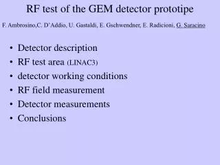
RF test of a small TPGdetector prototype F. Ambrosino,C. D’Addio, F. Caspers, U. Gastaldi, E. Gschwendtner, E. Radicioni, G. Saracino Edda Gschwendtner
Distance mm 10 cathode 3 Drift GEM1 1 T1 GEM2 T2 2 GEM3 1 Induction PAD TPGino • Triple GEM prototype designed and assembled at LNF (G. Bencivenni et al.) • GEM 10X10 cm2 standard geometry CERN • 40 PADs 2.5x1cm2 • 50 mm kapton cathode + 5 mm copper • 20 mm aluminizedmylar gas window • HARP preamplifier • Drift field: 3 kV/cm • T1=T2 field: 3 kV/cm • Induction field: 5 kV/cm • VG1= VG2= VG3=315 V • Total gain ~ 5x10³ • Gas: Ar:CO2 80:20 • 55Fe source (5.9 keV) Edda Gschwendtner
Detector Inside a 2 mm brass shielding: detector preamplifier HV distributor boards Edda Gschwendtner
RF test area at LINAC 3 GEM DETECTOR RF power supply RF pulse: 0.6 ms period of ~1.2 s Edda Gschwendtner
RF test setup L.V. power supply detector to RF tanks ~30cm Detector back to RF power supply ~1m H.V. power supply GEM DETECTOR Edda Gschwendtner
RF field measurement Agilent-HP 11955A biconical antenna to measure the RF field close to the detector area Edda Gschwendtner
RF field measurement 0.6ms Edda Gschwendtner
E-field from RF measurements With the known antenna factor AF and the signal VO of the RF from the antenna measured by the oscilloscope we calculated the electromagentic field E: AF(200MHz) = 16.7 dBm-1 V0=3 V AF= E(Volt/m)/ VO(Volt) 20 log10 E(Vm-1) = 20log10VO (V) + AF(dBm-1) E(Vm-1) = 10(logVo+ AF/20) = VO10AF/20 E=20 V/m Edda Gschwendtner
Noise response of the detector Noise response of the detector (no HV on GEM) Before shielding and grounding: ~400 mV peak to peak inside the RF pulse After shielding and grounding: ~20 mV peak to peak outside the RF pulse ~ 80 mV peak to peak inside the RF pulse With HV on the GEM: Noise response stays the same! RF no influence on detector, only on electronics, cables, etc… Edda Gschwendtner
Detector response to 55Fe X-ray 55Fe source: 5.9 keV peak and 3 keV escape peak. GEM working voltage: 3x315 V RF ON! Self-trigger Nb. This takes away one of the main worries: There is no sign of the photons hitting the GEMS) 55Fe spectrum Background spectrum Edda Gschwendtner
Detector response to 55Fe during RF pulse 55Fe source GEM working voltage: 3x315 V Trigger: RF signal from the antenna 55Fe pulse height: ~300mV Noise: ~40mV! Zoomed signal signal Edda Gschwendtner
Conclusion • We tested a GEM based detector, with cables and grounding not optimized for RF immunity, in the vicinity of the CERN LINAC 3 accelerator (2 RF accelerator tanks of 200 MHz, power supply of ~ 250 KW). • The noise response of the detector can be improved by a factor ~5 (400mV/80mV peak to peak) with home-made shielding of the cables, electronics, etc. • More effective and professional shielding can be provided in the MICE setup. Proof of concept is anyway valid. • The signal to noise ratio of a 55Fe X-ray source is ~8 (300mV/40mV) when the RF is on! • We were able to shield a GEM detector setup such that the presence of RF field at the order of E=20 V/m did not significantly increase the detector noise. Edda Gschwendtner
Pre-amps flexes Solenoid coil Field cage and support TPC active volume Shielding can Sketch-example of shielding principle for final chamber. (need to understand interference with steel shielding for PMTs etc..) All except field cage can be tested in situ early spring. Edda Gschwendtner