Download
1 / 86
870 likes | 907 Views
Data Link Layer Chapter 3 and 4 – Tanenbaum Chapter 5 and 6 - Kurose. General Concepts. Nodes: Hosts, Routers, Switches, Access point; Links : Communication channels connecting adjacent nodes; Frame : Information Units transferred:. global ISP. data-link layer has responsibility of

E N D
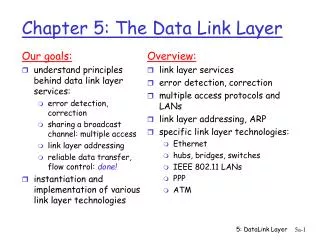
Data Link LayerChapter 3 and 4 – Tanenbaum Chapter 5 and 6 - Kurose
General Concepts • Nodes: Hosts, Routers, Switches, Access point; • Links: Communication channels connecting adjacent nodes; • Frame: Information Units transferred: global ISP data-link layer has responsibility of transferring datagram from one node to physically adjacent node over a link
Typical issues • How many bits will be transmitted at a time? How to delimit these bits? (Frames); • If a frame was destroyed how to fix it? (Retransmission); • If the acknowledge of a frame is destroyed how to correct it? (Dealing with duplicate frames); • How to regulate traffic if tx is faster than rx? • How to control access to a shared channel on broadcast networks?
Services Service without connection and without confirmation; Ex: Ethernet. • Service without connection with confirmation; Ex: WiFi • Service with connection and confirmation. (When links are long, unreliable);Ex: Satellites R E L I A B I L I T Y Nível Enlace
application transport network link link physical Whereis the link layer implemented? I/O Device: NIC (Network Interface Card) Example: Ethernet card; WiFi card; Combination of Hardware, Software, Firmware. cpu memory host bus (e.g., PCI) controller physical transmission network adapter card
Adaptors Communicating datagram datagram • Sending side: Receiving Side: • Encapsulates datagram Extract Datagram • Adds error checking, Looks for erros, controls...flow controls controller controller receiving host sending host datagram frame
Error Detection and Correction There are 2 strategies for handlingerrors: Forward Error Correction (FEC) code: It includes redundant information in each block of data so that the receiver can deduce the transmitted data. Used on channels that generate many errors. (Ex: wireless). Error Detection Code: It Includes enough redundancy only to allow the receiver to deduce that there was an error without identifying which. (Ex: fiber);Methods of detection in order of "strength": Parity, Checksum, CRC.
Medium Access Control - MAC • Point-to-point: Easy! • Broadcast networks: Shared medium (normally used in LANs) - it is necessary to determine who has the right to use the channel when there is a dispute for it. • Medium Access Control – MAC sublayer :The sublayer of the Link Layer that takes care of this task. shared RF (e.g., 802.11 WiFi) shared RF (satellite) shared wire (e.g., cabled Ethernet)
Channel Partitioning - FDMA Divide channel into smaller “pieces” (time slots, frequency, code) and allocate piece to node for exclusive use FDMA: frequency division multiple access • channel spectrum divided into frequency bands and each station assigned fixed frequency band • unused transmission time in frequency bands go idle • example: 6-station LAN, 1,3,4 have pkt, frequency bands 2,5,6 idle time frequency bands FDM cable
Channel Partitioning - TDMA TDMA: time division multiple access • access to channel in "rounds" • each station gets fixed length slot (length = pkt trans time) in each round • unused slots go idle • example: 6-station LAN, 1,3,4 have pkt, slots 2,5,6 idle 6-slot frame 6-slot frame 3 3 4 4 1 1
Dynamic Channel Allocation Key assumptions for formulating allocation problem: Station Model: N independent stations generate frames for transmission. Hypothesis: the randomness of arrival follows an exponential distribution (Poisson) makes the problem treatable though not exact; modeling traffic is a difficult research problem. Single Channel Assumption: the channel must be shared; Collision Assumption : two frames can overlap, and the resulting signal is adulterated. Frames that have suffered collisions must be retransmitted; Time: (a) Continuous Time: tx starts at any time;(b) Slotted Time: tx starts at the beginning of a slot Carrier Detection: (a) Carrier Sense (b) No Carrier Sense
CSMA / CD Carrier Sense Multiple Access with Collision Detection. Imagine: A dinner in a dark room. People around the table should listen, waiting for a period of silence, before speaking (Carrier Sense). When there is space, anyone has an equal chance to speak (Multiple Access). If two people speak at the same time, they detect the fact (Collision Detection) and stop talking. When a station detects a collision and stops the transmission, it must wait a random time to try to retransmit the packet.
CSMA / CD CSMA/CD can be in one of three states: contention, transmission, or idle. • Collisions can be detected by checking the power and pulse width of the received signal and comparing it with the transmitted signal.
CSMA - Collisions spatial layout of nodes • Propagation delay means two nodes may not hear each other’s transmission • collision: entire packet transmission time wasted Without Detection:
CSMA - CD • With Collision Detection : • colliding transmissions aborted, reducing channel wastage spatial layout of nodes
IEEE 802 • The IEEE standardized several LANs and MANs with the initials of IEEE 802. • Some survived, some no. Difficult to predict ... • Among the survivors: • IEEE 802.3 (Ethernet), • IEEE 802.11 (WiFi). • IEEE 802.15 (Bluetooth)
The most popular LAN. Bob Metcalfe spent the summer in Hawaii trying to connect islands via radio ... Classical Ethernet After the summer, already working in Xerox, the Ethernet system was born; 1978: DIX - created by DEC, Intel and Xerox. 1983: became the IEEE 802.3 standard. Metcalfe formed 3Com sold to HP in 2010
802.3 – Address • MAC address contains 6 bytes: • The first 3 assigned by the IEEE to organizations that build Ethernet interfaces; • The last 3 bytes are assigned by the organization. 1A-2F-BB-76-09-AD The first bit is 0 for unicast addresses and 1 for group addresses (Multicast). Address with all bits in 1 are received by all stations (Broadcast). LAN (wired or wireless) 71-65-F7-2B-08-53 58-23-D7-FA-20-B0 0C-C4-11-6F-E3-98
802.3 – Frame Format • Preamble: 7 bytes 10101010 - to signal occupation. Allows synchronization between receiver and transmitter clock (at bit level); • SoF – Start of Frame – 1 byte (10101011); • Type: indicates higher layer protocol (mostly IP) • Checksum – today CRC. Frame formats. (a) DIX Ethernet, (b) IEEE 802.3.
802.3 – Minimun size If the frame is too small, the transmission completes before A notices the collision and thus does not retransmit. For 10Mbps, on a cable of 2500m, the minimum size of the transmission is 64 bytes.
802-3 – Binary Exponential Backoff Algorithm • Time is divided into discrete slots of size equal to the worst round-trip (2t) propagation time. • After the first collision, each station waits 0 or 1 slot before trying again. • After the second collision, each station waits 0,1,2 or 3 slot times. • After i collisions, a random number between 0 and 2i-1 is chosen. It freezes in 1023 after 10 collisions.
Ethernet: unreliable, connectionless • Connectionless: no handshaking between sending and receiving NICs • Unreliable: receiving NIC doesnt send acks or nacks to sending NIC • data in dropped frames recovered only if initial sender uses higher layer rdt (e.g., TCP), otherwise dropped data lost • Ethernet’s MAC protocol: unslotted CSMA/CD with binary backoff
Fast Ethernet – 802.3u • IEEE Decision: Keep 802.3 making it faster = 100Mbps. Motivation: • Maintain existing cabling - compatibility with existing networks; • Fear of new protocol bring unexpected problems; • Keep the job. • It maintains the format of the packets, interfaces, rules and reduces bit time. • To ensure CSMA / CD continues to operate, a relationship must be maintained between minimum frame size and maximum cable size. Option: Decrease cable size.
GigabitEthernet • It maintains backwards compatibility with existing Ethernet standards. The most popular standardization was called IEEE 802.3ab • Full-duplex: CSMA/CD is not required; • Half-duplex: CSMA / CD is required – hubs. The speed is 100 times greater than the classic Ethernet, so the maximum distance would be 100 times smaller (25 meters). Strategies to increase this limit: • Carrier Extension: The hardware increases the frame size to 512 bytes, or • Framing Burst: Transmitter concatenates frames to send them together.
Gigabit Ethernet – Flow Control • If the receiver is busy, even for 1ms and does not read the input buffer, up to 1953 frames may accumulate. • And if a gigabit computer is transmitting to a computer on classic Ethernet? • Flow control is required: • PAUSE frames (type = 0x8808), telling you how long the pause should last. • A standard extension allows jumbo frames: up to 9KB.
Ethernet Evolution Causes of Ethernet success: simplicity, easy maintenance, low cost, IP compatibility. • 802.3ae – 10Gigabit Ethernet • 802.3ba-2010 – 40 e 100Gbps • Dec,2017 official IEEE 802.3bs => 400Gbps. • Towards Terabit Ethernet TbE (2020?)
ARP: Address Resolution Protocol Question:how to determine interface’s MAC address, knowing its IP address? ARP table: each IP node (host, router) on LAN has table • IP/MAC address mappings for some LAN nodes: < IP address; MAC address; TTL> • TTL (Time To Live): time after which address mapping will be forgotten (typically 20 min) 137.196.7.78 1A-2F-BB-76-09-AD 137.196.7.23 137.196.7.14 LAN 58-23-D7-FA-20-B0 0C-C4-11-6F-E3-98 137.196.7.88
ARP protocol: same LAN • A wants to send datagram to B • B’s MAC address not in A’s ARP table. • A broadcasts ARP query packet, containing B's IP address • dest MAC address = FF-FF-FF-FF-FF-FF • all nodes on LAN receive ARP query • B receives ARP packet, replies to A with its (B's) MAC address • frame sent to A’s MAC address (unicast) • A caches (saves) IP-to-MAC address pair in its ARP table until information becomes old (times out) • soft state: information that times out (goes away) unless refreshed • ARP is “plug-and-play”: • nodes create their ARP tables without intervention from net administrator
111.111.111.110 E6-E9-00-17-BB-4B 222.222.222.222 49-BD-D2-C7-56-2A Addressing: routing to another LAN walkthrough: send datagram from A to B via R • focus on addressing – at IP (datagram) and MAC layer (frame) • assume A knows B’s IP address • assume A knows IP address of first hop router, R (how?) • assume A knows R’s MAC address (how?) B A R 111.111.111.111 74-29-9C-E8-FF-55 222.222.222.220 1A-23-F9-CD-06-9B 222.222.222.221 111.111.111.112 88-B2-2F-54-1A-0F CC-49-DE-D0-AB-7D
MAC src: 74-29-9C-E8-FF-55 MAC dest: E6-E9-00-17-BB-4B IP src: 111.111.111.111 IP dest: 222.222.222.222 IP Eth Phy 111.111.111.110 E6-E9-00-17-BB-4B 222.222.222.222 49-BD-D2-C7-56-2A Addressing: routing to another LAN • A creates IP datagram with IP source A, destination B • A creates link-layer frame with R's MAC address as dest, frame contains A-to-B IP datagram B A R 111.111.111.111 74-29-9C-E8-FF-55 222.222.222.220 1A-23-F9-CD-06-9B 222.222.222.221 111.111.111.112 88-B2-2F-54-1A-0F CC-49-DE-D0-AB-7D
MAC src: 74-29-9C-E8-FF-55 MAC dest: E6-E9-00-17-BB-4B IP src: 111.111.111.111 IP dest: 222.222.222.222 IP Eth Phy IP src: 111.111.111.111 IP dest: 222.222.222.222 IP Eth Phy 111.111.111.110 E6-E9-00-17-BB-4B 222.222.222.222 49-BD-D2-C7-56-2A Addressing: routing to another LAN • frame sent from A to R • frame received at R, datagram removed, passed up to IP B A R 111.111.111.111 74-29-9C-E8-FF-55 222.222.222.220 1A-23-F9-CD-06-9B 222.222.222.221 111.111.111.112 88-B2-2F-54-1A-0F CC-49-DE-D0-AB-7D
IP Eth Phy MAC src: 1A-23-F9-CD-06-9B MAC dest: 49-BD-D2-C7-56-2A IP Eth Phy IP src: 111.111.111.111 IP dest: 222.222.222.222 111.111.111.110 E6-E9-00-17-BB-4B 222.222.222.222 49-BD-D2-C7-56-2A Addressing: routing to another LAN • R forwards datagram with IP source A, destination B • R creates link-layer frame with B's MAC address as dest, frame contains A-to-B IP datagram B A R 111.111.111.111 74-29-9C-E8-FF-55 222.222.222.220 1A-23-F9-CD-06-9B 222.222.222.221 111.111.111.112 88-B2-2F-54-1A-0F CC-49-DE-D0-AB-7D
IP Eth Phy MAC src: 1A-23-F9-CD-06-9B MAC dest: 49-BD-D2-C7-56-2A IP Eth Phy IP src: 111.111.111.111 IP dest: 222.222.222.222 111.111.111.110 E6-E9-00-17-BB-4B 222.222.222.222 49-BD-D2-C7-56-2A Addressing: routing to another LAN • R forwards datagram with IP source A, destination B • R creates link-layer frame with B's MAC address as dest, frame contains A-to-B IP datagram B A R 111.111.111.111 74-29-9C-E8-FF-55 222.222.222.220 1A-23-F9-CD-06-9B 222.222.222.221 111.111.111.112 88-B2-2F-54-1A-0F CC-49-DE-D0-AB-7D Link Layer
IP Eth Phy MAC src: 1A-23-F9-CD-06-9B MAC dest: 49-BD-D2-C7-56-2A IP src: 111.111.111.111 IP dest: 222.222.222.222 111.111.111.110 E6-E9-00-17-BB-4B 222.222.222.222 49-BD-D2-C7-56-2A Addressing: routing to another LAN • R forwards datagram with IP source A, destination B • R creates link-layer frame with B's MAC address as dest, frame contains A-to-B IP datagram B A R 111.111.111.111 74-29-9C-E8-FF-55 222.222.222.220 1A-23-F9-CD-06-9B 222.222.222.221 111.111.111.112 88-B2-2F-54-1A-0F CC-49-DE-D0-AB-7D
Ethernet switch • link-layer device: • store, forward Ethernet frames • examine incoming frame’s MAC address, selectively forward frame to one-or-more outgoing links when frame is to be forwarded on segment, uses CSMA/CD to access segment • transparent • hosts are unaware of presence of switches • plug-and-play, self-learning A B C’ 1 2 6 4 5 3 B’ C A’ switch with six interfaces (1,2,3,4,5,6)
Source: A Dest: A’ MAC addr interface TTL 60 1 A A A’ Switch: self-learning • switchlearnswhich hosts can be reached through which interfaces • when frame received, switch “learns” location of sender: incoming LAN segment • records sender/location pair in switch table A B C’ 1 2 6 4 5 3 B’ C A’ Switch table (initially empty)
Switch: frame filtering/forwarding when frame received at switch: 1. record incoming link, MAC address of sending host 2. index switch table using MAC destination address 3. ifentry found for destination then { ifdestination on segment from which frame arrived then drop frame else forward frame on interface indicated by entry } else flood /* forward on all interfaces except arriving interface */
Source: A Dest: A’ A’ A MAC addr interface TTL 60 60 4 1 A A’ A A’ A A’ A A’ A A’ A A’ A A’ Self-learning, forwarding: example • frame destination, A’, locaton unknown: flood A B • destination A location known: C’ selectively send on just one link 1 2 6 4 5 3 B’ C A’ switch table (initially empty)
Institutional network mail server to external network web server router IP subnet
network link physical link physical datagram datagram frame frame frame Switches vs. routers application transport network link physical both are store-and-forward: • routers: network-layer devices (examine network-layer headers) • switches: link-layer devices (examine link-layer headers) both have forwarding tables: • routers: compute tables using routing algorithms, IP addresses • switches: learn forwarding table using flooding, learning, MAC addresses switch application transport network link physical
Virtual LAN: motivation Earlier, geography overcome logic: if two employees worked in the same room they were on the same LAN; a physical change has implied in LAN change; For flexibility, it is interesting to decouple the physical network from logic (via software!). Reasons to organize who is on which LAN: • Safety; • Load; • Broadcast traffic - broadcast storm overloads the network 41
7 1 2 8 15 9 10 16 VLANs port-based VLAN: switch ports grouped (by switch management software) so that singlephysical switch …… Virtual Local Area Network 15 7 9 1 2 8 10 16 switch(es) supporting VLAN capabilities can be configured to define multiple virtualLANS over single physical LAN infrastructure. … … Computer Science (VLAN ports 9-15) Electrical Engineering (VLAN ports 1-8) … operates as multiplevirtual switches … … Computer Science (VLAN ports 9-16) Electrical Engineering (VLAN ports 1-8)
forwarding between VLANS: done via routing (just as with separate switches) • in practice vendors sell combined switches plus routers Port-based VLAN router • traffic isolation:frames to/from ports 1-8 can only reach ports 1-8 • can also define VLAN based on MAC addresses of endpoints, rather than switch port 15 7 9 1 2 8 10 16 • Consider: • CS user moves office to EE, but wants connect to CS switch? … … Computer Science (VLAN ports 9-15) Electrical Engineering (VLAN ports 1-8) • dynamic membership: ports can be dynamically assigned among VLANs
1 16 VLANS spanning multiple switches • trunk port:carries frames between VLANS defined over multiple physical switches • frames forwarded within VLAN between switches can’t be vanilla 802.1 frames (must carry VLAN ID info) • 802.1q protocol adds/removed additional header fields for frames forwarded between trunk ports 15 7 9 7 1 3 5 2 8 10 4 6 2 8 … … Computer Science (VLAN ports 9-15) Ports 2,3,5 belong to EE VLAN Ports 4,6,7,8 belong to CS VLAN Electrical Engineering (VLAN ports 1-8)
802.1Q VLAN frame format type source address dest. address preamble data (payload) 802.1 frame CRC type 802.1Q frame data (payload) CRC Recomputed CRC 802.1Q Header 2-byte Tag Protocol Identifier (value: 81-00) source address dest. address preamble Tag Control Information (12 bit VLAN ID field, 3 bit priority field like IP TOS)
Data center networks • 10’s to 100’s of thousands of hosts, often closely coupled, in close proximity: • e-business (e.g. Amazon) • content-servers (e.g., YouTube, Akamai, Apple, Microsoft) • search engines, data mining (e.g., Google) • challenges: • multiple applications, each serving massive numbers of clients • managing/balancing load, avoiding processing, networking, data bottlenecks Inside a 40-ft Microsoft container, Chicago data center
Data center networks • load balancer: application-layer routing • receives external client requests • directs workload within data center • returns results to external client (hiding data center internals from client) Internet Border router Load balancer Load balancer Access router Tier-1 switches B A C Tier-2 switches TOR switches Server racks 7 6 5 4 8 3 2 1
Data center networks • rich interconnection among switches, racks: • increased throughput between racks (multiple routing paths possible) • increased reliability via redundancy Tier-1 switches Tier-2 switches TOR switches Server racks 7 6 5 4 8 3 2 1
Wired vs Wireless Wireless Positive: • Ease of Installation • Mobility • Cost reduction Negative: • Lower Transmission Band • Error Rates • Complex Routing • Devices with reduced computational power • Safety
Wireless Link Characteristics (1) important differences from wired link …. • decreased signal strength: radio signal attenuates as it propagates through matter (path loss) • interference from other sources: standardized wireless network frequencies (e.g., 2.4 GHz) shared by other devices (e.g., phone); devices (motors) interfere as well • multipath propagation: radio signal reflects off objects ground, arriving ad destination at slightly different times …. make communication across (even a point to point) wireless link much more “difficult”