Download
1 / 18
180 likes | 334 Views
Communication System for the AAUSAT-II. Kresten K. Sørensen kkso02@space.aau.dk Department of Control Engineering Aalborg University. AAUSAT-II Mission Objectives. Education Communication (One-way and two-way) Attitude Determination & Control System (Detumbling and pointing)

E N D
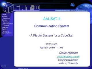
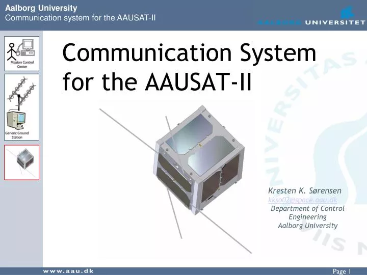
Communication Systemfor the AAUSAT-II Kresten K. Sørensen kkso02@space.aau.dk Department of Control Engineering Aalborg University
AAUSAT-II Mission Objectives • Education • Communication • (One-way and two-way) • Attitude Determination & Control System • (Detumbling and pointing) • Payload (Gamma Ray Detector) • Deploy extra solar panels • Upload new software for radio amateur use
AAUSAT-II Overview MECH - Mechanical structure OBC – Onboard Computer CDH – Command Data Handler COM – Communication EPS – Electrical Power Supply P/L – Payload ADCS – Attitude Determination and Control System GND – Ground station MCC – Mission Control Center
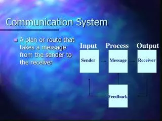
COM System • Purpose • To create a communication path between the satellite and Earth. • Demands • Simple, robust design • Power saving • Small • Interface to: CAN, RS232, and Radio
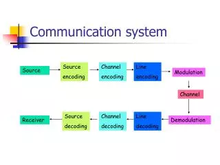
Block Diagram • Components • MCU • Radio • CAN • UART • Modem
Specifications for COM 1/2 Radio Frequency: 437.425 MHz (Half duplex) 6 kHz bandwidth Data rates: 1200/2400/4800 bit/sec FFSK/MSK-modulation Transmitter Power: 0.5 W Link budget: (Worst case) Downlink margin 6,2 dB Uplink margin 20,5 dB CAN bus: 125 kbps
Specifications for COM 2/2 Mass incl. Antenna: 110g Supply voltage: 3.3 V Power Consumption Listening: 184.8 mW Receiving: 283.8 mW Transmitting: 2085.6 mW
Modulation options • FSK - Frequency Shift Keying • MSK - Minimum Shift Keying • GMSK - Gaussian Minimum Shift Keying
MSK Modulation • Advantages of MSK modem • Good noise performance compared to FSK • Easy to use • Disadvantages for MSK modem • Synchronous interface • Synchronization • Data must be synchronized to clock • The modem synchronize automatically on bit level • Synchronization on byte level must be done in software on the MCU
Clock Divider • Adds the possibility of bit rates down to 150 bps by dividing the data clock with 1, 2, 4 or 8 • Gives more than one symbol per bit and makes the signal easier to demodulate.
Basic Beacon • Basic Beacon format: AAUSATII <data> • AAUSATII sent as Morse code on FM • An 800 Hz Morse tone is sent to the radio • Makes it easier to find the satellite • Morse tone created with the MCU PWM generator and a low-pass filter • Data is modulated by the modem • 6 bit battery voltage + 2 bit counter After low-pass filter
Protocol • Connectionless AX.25 using UI frames • Flags used for synchronization • Header for identification of packets • Checksum for verification of packet contents • Connection orientated AX.25 is to difficult to implement considering our demands • The connection orientation is placed on a higher level on the OBC and GND server.
Software • Software tasks • Relay data between GND and CDH • Send basic beacon • Collect housekeeping data • Interfaces • CAN bus • USART for modem and radio • UART for GND segment and debugging
Software Structure • Interrupt module • External communication functions • Time critical functions Main module • Internal functions • Non time critical functions
Synchronization • Synchronous bit stream without start and stop bits • Hardware synchronization difficult • The AX.25 flag is used for synchronization • Synchronization is done by the ISR CD 101111001001111110011111100111111001 ISR sync.