Download
1 / 45
450 likes | 525 Views
Machine Vision for the Life Sciences. Presented by: Niels Wartenberg June 12, 2012. Track, Trace & Control Solutions. Niels Wartenberg Microscan Sr. Applications Engineer, Clinical

E N D
Machine Vision for the Life Sciences Presented by: Niels Wartenberg June 12, 2012 Track, Trace & Control Solutions
Niels Wartenberg Microscan Sr. Applications Engineer, Clinical Senior Applications Engineer on Microscan's Clinical Team and regular instructor of identification technologycourses, Mr. Wartenberg has been part of the Microscan Team since 2000. Prior to joining Microscan he gathered over 8 years experience implementing solutions in clinical laboratory systems.
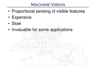
is increasingly adopted as an effective means of automating critical processes and increasing laboratory throughput Machine Vision
Faster More Repeatable
Machine Vision and Auto ID Converge • Microscan legacy: • 30+ years in Auto ID • 30+ years in Machine Vision • Read bar codes, PLUS: • Measure Vials • Check Fill Level • Verify Cap Alignment • …and More
Agenda • Machine Vision Basics • Definitions • Uses in the Life Sciences • System Configurations • Smart Cameras • PC-based Systems • Software Tools • Image Processing • Image Analysis • Typical Applications • Identification • Inspection • Measurement • Robotic Guidance
MACHINE VISION The automatic extraction of information from digital images.
Examples of Useful Information • Presence/Absence of a Component • Location/ Orientation of an Object • Reading of a Human or Machine Readable Code • Non-Contact Measurement of a Dimension
Application Examples • Reading 1D symbols on microplates • Reading 2D symbols on vials/racks • Detecting correct orientation of slides • Inspecting print quality on tubes • Inspecting drops of dispensed liquid • Guiding a lab robot to pick & place specimen tubes • Check presence/absence of consumables (e.g. pipette tips, vials or other labware)
COMMUNICATION PROCESSING SENSOR LENS LIGHTING PART PART
Lighting • Proper lighting is essential to a successful machine vision application • Reveals features we want to detect/analyze • Minimizes everything else • Key choices • Type of light • Light placement with respect to the part and camera • Surface geometry & texture of part are key factors in determining lighting Generally, if the feature cannot be seen, it cannot be analyzed
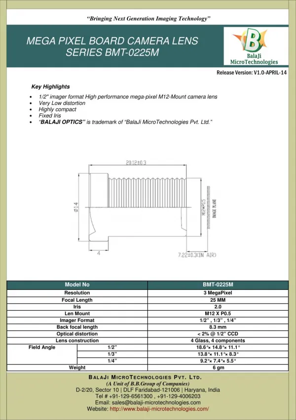
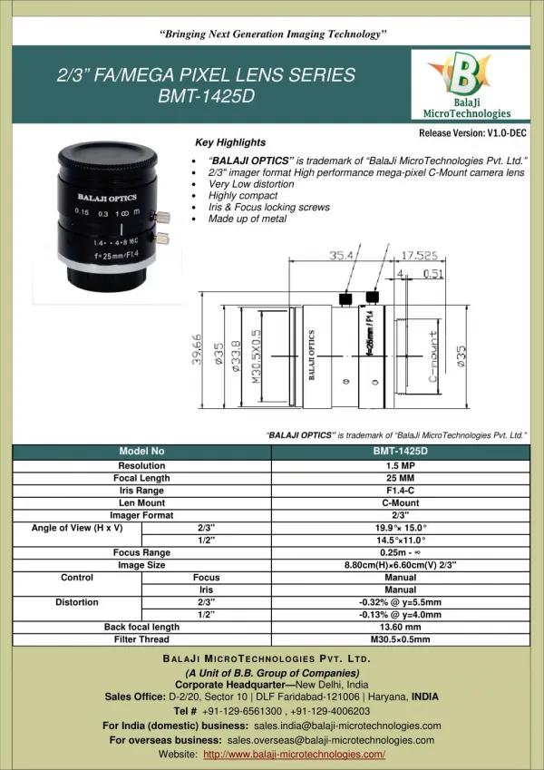
Lens • Gather light & deliver to the image sensor • Determine: • Focal Point • Field of View (FOV) • Depth of Focus Lens & extension tubes
Lens Configurations • Fixed, interchangeable lenses • C-Mount standard • Used with standard or smart cameras • Autofocus lenses • Mechanical or liquid lens autofocus • Used in fully integrated imagers
Image Sensors Sensor is inside the camera • Captures light and converts it to a digital image • More pixels = more detail • Higher resolution required when: • Resolving the narrow line in a small bar code • Seeing small defect on a part • Making a precise dimensional measurement .3MP sensor 2MP sensor
Machine Vision Cameras • Digital cameras • Most modern machine vision cameras • Alternative standards • Camera Link • Firewire (IEEE 1394) • USB (2.0 and 3.0) • GigE
GigE Vision® Standard • GigE Vision standard • Developed by the Automated Imaging Association (AIA) • Adopted by industry • Advantages over other standards • GigE Vision advantages • High bandwidth for fast transfer of large images • Uncompromised transfer up to 100 meters • Standard h/w & cables for easy, low cost integration • Standard h/w to connect multiple cameras to single/multiple computers • Highly scalable to follow Ethernet bandwidth to 10GigE & beyond
Software Tools
Vision Processing Steps ImageAnalysis Decision Logic • Modify the image to make features stand out Communicate Results ImageProcessing AcquireImage • Extract features from the image • Measure features and compare to specification • Communicate Pass/Fail decisions and other data
Image Processing vs. Image Analysis Tools • Image Processing • Original Image -> New Image • Used to make image easier to interpret or analyze • Image Analysis • Image -> Features • Typical features include an edge, line, object, etc.
Image Processing Tool Examples • Image arithmetic • Image warping • Binary & grayscale morphology
Image Warping • Often used prior to OCR (Optical Character Recognition) • Rotate text viewed at an angle • Unwrap text printed on an arc or a circle
Morphology • Transforms the image to make certain features stand out • Use to expand, separate, merge, clean • Does not extract features Erode black pixels: Create separation and then count Dilate white pixels: Increase Data Matrix cell size
Image Analysis Tool Examples • The Blob Tool • Edge Detection • Pattern Matching • 1D & 2D Symbols • OCR & OCV • Dynamic ROI Location • Measurement Resolution
The Blob Tool • A blob is a group of connected pixels within a size range • similar color (shade of gray) • differ from surrounding area • Typical applications • Count number of parts • Locate position of a part • Measure size of a part • Compare to a tolerance Measure: Check size to ensure parts are not broken Count: Verify that all wires are installed
Edge Detection • Edge tools scan an image along a user-specified direction • Detect transitions between two regions of different intensity • Fit a line, circle or ellipse to the edge data • Applications • Detect or locate an object • Measure a distance • Locate a corner • Measure an angle
Vector Edge Detection • Edges can be detected along user defined directions (vectors)
Edge Tool Usage Locate: Use two Edge tools to find a corner Measure: Measure fill level of a container or detect cap tightness Locate: Check label placement
Finding Patterns in an Image • Normalized correlation based template matching • Scans template across image and identifies best match • Affected if part of what is in the template is missing from the image being analyzed • Geometric edge pattern matching • Matches patterns of edges in the image and the template • Is not affected if part of the template is missing in the image or if the polarity of the image is reversed
Pattern Matching • Pattern matching tools learn the outline of a part of pattern • Scans across image and identifies best match • Locates pattern with sub-pixel accuracy Intellifind Tool Example
1D & 2D Symbols • Linear (1D) Bar Code Symbols • Limited data storage • Height provides redundancy • Requires higher contrast • 2D Symbols (ie, Data Matrix) • Data encoded in both height & width • Readable 360° • Contrast as low as 20%
OCR - Optical Character Recognition • Decodes human readable text • Can handle dot matrix & dot peen printing • Noisy backgrounds • Uneven lighting • Trainable • Neural Network based • Character addition/deletion • Tolerates scale changes
OCV – Optical Character Verification • Typical Application • Checking correctness and legibility of a printed label or text • Detects printing defects
OCR vs. OCV • Terms often used incorrectly – NOT the same • OCR: Optical Character Recognition • OCV: Optical Character Verification • OCR – an automatic identification tool • Intended to decode human readable information • OCV – a print quality inspection tool • Intended to flag & reject poor quality text
ROIsPositioned ROIs After Part Motion ROIs Corrected ForPart Movement Dynamic ROI Location • Relocating regions of interest (ROI) to compensate for part position and rotation
Nominal Measurement Resolution Example: • Paper Clip = 1.0 " • Image width = 1280 Pixels • Resolution = • 1.0 " /1280 Pixels • = .0008 " /Pixel Example: • Car = 13.5’ • Image width = 1280 Pixels • Resolution = • 13.5’ / 1280 Pixels • 162’’ /1280 Pixels • = .127" /Pixel
Actual Measurement Resolution • Depends on: • Sensor resolution • Field of View(FOV) • Sub-pixel capability of vision processing tools
Typical Applications
Automatic Identification Applications • Specimen ID • Reagent ID • Tube carrier ID • Microtiter plate ID • Microtiter vial ID
Tube & Cap Inspection • Application requirements • Rack location • Bar code reading • Tube/cap inspection • Solution • Camera • Custom GUI
Vision Guided Motion Applications • Application requirements • Determine object location & orientation • Calibration in real world units • Robust & accurate pattern matching • Application examples • Robotic tube pick & place • Colony picking
Machine Vision • Automate critical processes • Increase throughput • Achieve verifiable process repeatability
Thank You If you have questions regarding this webinar or topic, please an e-mail to info@microscan.com. For further information about machine vision, visit our website at www.microscan.com.