Download
1 / 34
340 likes | 461 Views
John Matheson Rutherford Appleton Laboratory On behalf of the SP Community. Thanks to Martin Gibson (RAL), Richard Holt (RAL), Dave Lynn (BNL), Peter Phillips (RAL) and Giulio Villani (RAL). Outline. • powering issues for the ATLAS strip tracker upgrade

E N D
John Matheson Rutherford Appleton Laboratory On behalf of the SP Community Thanks to Martin Gibson (RAL), Richard Holt (RAL), Dave Lynn (BNL), Peter Phillips (RAL) and Giulio Villani (RAL)
Outline • powering issues for the ATLAS strip tracker upgrade the serially powered (SP) detector stave shunt regulator options protection against chain failure current source developments the SP stavelet program SP stavelet test results summary and conclusions
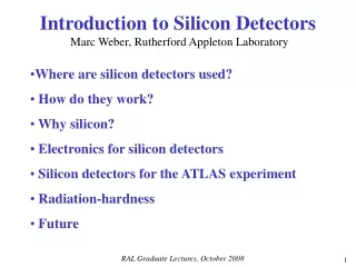
The present SCT • 4088 Detector Modules • 3.2M channels • Independent Powering • 4088 cable chains • 22 PS racks • 4 crates / rack • 48 LV and 48 HV channels/crate • Overall efficiency ~40% • Cable R => voltage drops current SCT module design Upgrade Tracker: need 34 M channels to cope with increased luminosity 768 chan/side
Upgrade strip tracker: Stave and Petal Concept detector module: 10 by 10cm Si 4 columns of strips 40 ABCN-25 chips 5120 channels detector staves arranged into barrels detector petals arranged into discs
Serially Powered Stave Architecture 24 hybrids in series, each at different potential wrt GND Common GND at end of stave CLK & COM AC coupled at hybrid DATA AC coupled at end of stave staves carry 12 detectors, 24 readout hybrids per side each hybrid carries 20 ABCN ROICs each module must carry a shunt regulator to keep supply V constant powering by DC-DC converter is a competing/complementary option currently prototyping 4 module “Stavelets”
Shunt Regulator Architectures with ABCN-25 • Hybrid with Shunt “W” • Use each ABCN-25 integrated shunt regulator • Use each ABCN-25 integrated shunt transistor(s) • Hybrid with Shunt “M” • Use one external shunt regulator • Use each ABCN-25 integrated shunt transistor(s) • Two (redundant) shunt transistors, 140mA each • Hybrid with SPi (or similar) • Use one external shunt regulator • Use one external power transistor
Protection of SP against faults What happens if a module fails open circuit? What happens if a module becomes a noise generator? How to turn modules on/off? We could provide a system to “short out” each module under control of DCS Voltage across shorted module should be small Area of components and number of control lines must be small Protection circuit must draw minimal power when module active Automatic over voltage protection is desirable
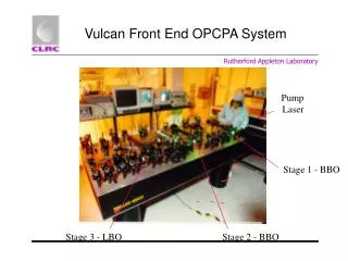
Programmable Constant Current source • programmablecurrent source has been prototyped (J.Stastny, ASCR) • specifically designed for stave09 (ABCN-25), output up to 80V at 6A • current setting resolution 2mA • isolated USB interface • overvoltage protection • it should work well also for ABCN-13 • now under test with stavelets at RAL
The Stavelet with ABCN-25 readout EOS card PPB PCB power and power control communication (SPI) data and hybrid communication (BCC) BCC PCB bus cable cooling Allows comparison of: Different power configurations, Different bus cable designs, Different grounding and shielding concepts Stavelets allow option choices for later stave construction One built, second under costruction at RAL PPB carries protection and power plugin
Power Protection board (PPB) and plugins PPB dual redundant distributed shunt plugin SPI plugin PPB provided by BNL, implements protection scheme and power connectivity Hybrid contains basic control circuit for distributed shunt – used for stavelet tests so far Plug in boards will be used for testing other powering schemes – coming soon ! serial power interface chip (SPI) Fermilab
Stavelet GAIN @2fC, JS CS II@5A After Trimming, reading all hybrids simultaneously, column 1 strip order corrected. Anomalous Cal Line
Stavelet ENC @2fC, JS CS II@5A After Trimming, reading all hybrids simultaneously, column 1 strip order corrected.
Thermal images of stavelet in operation All hybrids on 22.7V 5.09A Slow control disables odd hybrids 12.7V 5.09A Slow control disables even hybrids
0.5 W Thermal images of slow control bypass in operation slow control bypass on: P = VI = 100mV * 5A = 0.5W thermal images show slow control bypass working as expected
Stavelet GAIN @2fC, JS CS II@5A After Trimming, even hybrids bypassed, column 1 strip order corrected. Anomalous Cal Line
Stavelet ENC @2fC, JS CS II@5A After Trimming, even hybrids bypassed, column 1 strip order corrected.
Summary and Next Steps • Progress continues with Serial powering for the tracker Upgrade • ABCn-25 chips contain custom SP components • A protection system has been implemented using COTS components • The protection system also implements slow control of powering • A custom current source has been prototyped • The first test stavelet has been built • Stavelet working well so far, no excess noise. Modules can be turned on and off independently. Studies continue. • Stavelets will allow refinement of architecture for a full SP stave prototype • A modified stavelet is being designed (R.Wastie et al.) to allow DC-DC tests (with G.Blanchot, F.Faccio) and will be built asap
Power Requirements with Modern Process Technologies Power per 128 channel chip per channel In ATLAS SCT ABCD (0.8m, biCMOS) Digital: Analogue: 4.0 volts 3.5 volts 35 mA per chip (actual) 74 mA per chip (actual) => 4.0 x 35 + 3.5 x 74 = 399 mW 3.1 mW Present Prototype ABCN25 (0.25m CMOS) Digital: Analogue: 2.5 volts 2.2 volts 95 mA per chip (preliminary) 27 mA per chip (preliminary) => 2.5 x 95 + 2.2 x 27 = 300 mW 2.3 mW Proposed ABCN13 (0.13m CMOS) Digital: Analogue: 0.9 volts 1.2 volts 51 mA per chip (estimate) 16 mA per chip (estimate) => 0.9 x 51 + 1.2 x 16 = 65 mW 0.5 mW ** ** • ABCN25: Vdig > Vana Idig >> Iana • If we generate Vana from Vdig using LR: • 27mA * 0.3V = 8.1mW per chip • 3% of chip power • ABCN13: Vana > Vdig Idig >> Iana • If we generate Vdig from Vana using LR: • 95mA * 0.3V = 28.5mW per chip • 44% of chip power • Can we do better than this? Of course… ** Power Estimates for an ABCN in 130nm Technology, Mitch Newcomer, Atlas Tracking Upgrade workshop, NIKHEF, November 2008 http://indico.cern.ch/getFile.py/access?contribId=16&sessionId=8&resId=0&materialId=slides&confId=32084
ABCN-13 hybrid current ABCN-13 hybrid voltage n = number of hybrids these numbers for ABCN-13, i.e. next ASIC generation
Richard Holt – Rutherford Appleton Laboratory Detector power efficiency Two-stage DC-DC powering (78% hybrid efficiency) 1 stave = 24 hybrids = 480 ABC-N (0.13 m) Power (voltage) 34 Watts 1.3 Watts 9 Watts 76 Watts 32 Watts Efficiency = 42% D Cables assumed to be 2 ohms total for each power line pair Regulator power = (1/eff - 1) x ABC power Stave supply current = (32 + 9)watts / 10volts = 4.1amps Numbers rounded 17
Richard Holt – Rutherford Appleton Laboratory Detector power efficiency Serial powering a stave, (no DC-DC version) 1 stave = 24 hybrids = 480 ABC-N (0.13 m) Power (constant current) 5.1 Watts 0.5 Watts 52 Watts 14 Watts (70% efficiency ) H 32 Watts Efficiency = 62% D Cables assumed to be 2 ohms total for each power line pair Regulator power = (1/eff - 1) x ABC power H Stave supply current = (32 + 14)watts / (1.2volts x 24) = 1.6amps Numbers rounded 18
Richard Holt – Rutherford Appleton Laboratory Detector power efficiency Serial powering a stave, (higher voltage, with DC-DC version) 1 stave = 24 hybrids = 480 ABC-N (0.13 m) Power (constant current) 2.4 Watts 0.5 Watts 43 Watts 8.5 Watts 32 Watts Efficiency = 74% D Cables assumed to be 2 ohms total for each power line pair Regulator power = (1/eff - 1) x ABC power H Stave supply current = (32 + 8.5)watts / (1.6volts x 24) = 1.1amps Numbers rounded 19
Efficiency = power consumed by ABCN H power delivered to hybrid Highest Efficiency:SP with on-chip DC-DC conversion using switched capacitors Lowest Noise:SP with on-chip Linear Regulatorsfor both Analogue and Digital Eff = 55%Eff = 50% Eff = 77%Eff = 75% Efficiency = H H D D power consumed by ABCN D power delivered by power supply Two possible future SP implementations Some assumptions: Cable resistance 2 ohms for each line pair, SR = 85%, low current DC-DC = 90%, high current DC-DC = 85% Bus cable traces 7.5mm wide, 18 micron Cu chip power is that projected for 130nm ABCn ABCN demand power is dependent on task. This will normally mean a shunt regulator will dissipate some power to maintain voltage under all conditions.
Shunt regulator schemes Data communication Power management Monitoring/alarms Designed by Marcel Trimpl (FNL) Mitch Newcomer (U Penn) The SPI chip – a serial power test bed SPi (Serial Power Interface): • flip chip, bump bonded • 144 pads (68 I/O, 76 power) • Sub-set used for each application 2.7 mm 5.5 mm
Serial Powering system design Current Source ver.2 specifications: Input Voltage 90 - 264 VAC Input Frequency 47 - 63 Hz Input Power 800 W (max) Output Current range 0 – 6 A Output Current Setting Resolution 2 mA Output Current Settling Time < 2 ms Voltage Compliance 0 – 80 V Voltage Resolution 25 mV Output Current Ripple (Pk-Pk) 10 mA (estimated max) Control Manual / Remote(USB) Mechanical Dimensions (W x D x H) 305 x 280 x 133 mm 4
Serial Powering and HV Standard HV powering: one HV per hybrid Alternative HV powering: one HV supply per 2 hybrids • Serial Powering is compatible with the use of a single HV supply for several modules • Each sensor is dynamically connected to current source ground through output impedances of the chain of shunt regulators • Low shunt output impedance is crucial to achieve good ‘grounding’ and reduce noise
AC coupled data transmission - prototype bus tape Whether we use SP or not, need to minimize number of signal traces in stave => multi-drop Test stave at Oxford Cu/kapton + Al screen layer Send “TTC” data from FPGA 24 dummy hybrids with receiver/drivers Loopback data on dummy hybrids FPGA BERT. Measure BERT for balanced and unbalanced data, parallel and serial powering Balanced code works fine. M-LVDS + Serial powering + balanced code ok, ie no errors found in 3 locations tested (3 ,12 and 24).
Stavelet construction at RAL Glue pattern trials (left - on test board , right – on test bus cable) Module placement area Module placement arm Rotate stage Y stage ZX stages Stavelet test box 6
Hybrid powering • Hybrids are designed for two powering schemes: • Parallel power, which could be provided by DCDC converters • Shunt regulation, using the distributed shunt regulators integrated within the ABCN-25s • Required for serial powering – Mshunt is the default scheme Mshunt characteristic for single and dual shunts enabled per ABCN-25 on a 20 ASIC hybrid (expect max. Hybrid shunted current to be ≤5A) Single Shunt transistor enabled per ABCN-25 (20 x shunt transistors) Shunt regulates Vhybrid to 2.5V at Is>3.5A and diverges at Is<6.5A (cf Ihybrid +Ismax (3.6 + (20 x 0.14))) = 6.4A Dual Shunt transistors enabled per ABCN-25 (40 x shunt transistors) Shunt regulates Vhybrid to 2.5V at Is>3.5A and diverges at I<9.5A (cf Ihybrid +Ismax (3.6 + (40 x 0.14))) = 9.2A