Download

1 / 56
720 likes | 1.1k Views
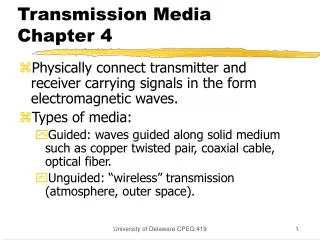
Chapter 4 GAS FILTRATION MEDIA. T. J Ptak, PhD Columbus Industries, Inc. VP of Research and Development. OVERVIEW. 4-1 What is filter media 4-2 Parameters of filter media 4-3 Filter media classification Depth S urface 4-4 Types of filter media Fibrous filter media

E N D
Chapter 4GAS FILTRATION MEDIA T. J Ptak, PhD Columbus Industries, Inc. VP of Research and Development
OVERVIEW • 4-1 What is filter media • 4-2 Parameters of filter media • 4-3 Filter media classification • Depth • Surface • 4-4 Types of filter media • Fibrous filter media • Electrostatically enhanced • Nano-fibers • 4-5 Filter media test methods • 4-6 Design process
4-1 FILTER MEDIA ModelCharacteristics pressure drop, efficiency, filter life, cost fiber or granule diameter basis weight, thickness, permeability, pore size
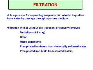
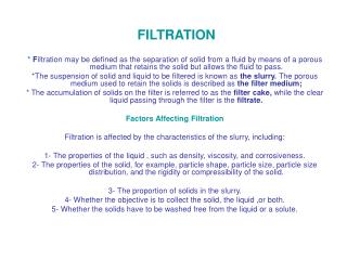
FILTER MEDIA • Purpose: • Cause a separation of particulate solids from a flowing fluid with a minimum consumption of energy • Very broad classification based on: • service life • filtration principle
4-2 PARAMETERS OF FILTER MEDIA • Basis weight: Defined as the weight of media per unit area. Expressed in pounds per 3,000 sq. feet. Metric values are expressed in g/m2 and can be calculated by multiplying basis weight in lb./3000 ft2 by 1.627. • Thickness: Thickness of flat papers is measured with dead weight type caliper gauge having typically a pressure foot of 0.25” diameter and exerting a load of 4 lb./in2. • Permeability: Air permeability is the flow rate of air at 23oC through a sheet of paper under a specified pressure head, usually expressed as CFM per square foot of area at the 0.50 in. water pressure. Often called as Frazier permeability. Objectives: What parameters describe filter media.
PARAMETERS OF FILTER MEDIA • Maximum pore size: Defined as the largest pore. Expressed as a pressure (P) of air in inches of water recorded when the first air bubble appears in the fluid. The size of largest pore (r) can be calculated: gis the surface tension and is the contact angle. • Burst strength: Is defined as the hydrostatic pressure in psi required to produce rapture of paper sample when pressure is increased at the controlled rate through a rubber diaphragm to a circular area of 1.2 in. diameter. • Stiffness: Ability to resist an applied bending force.
PARAMETERS OF FILTER MEDIA • Tensile strength: The Tensile Strength Test is a measure of the directional strength of the media, measured in pounds per square inch. • Electrostatic charge • Filtration efficiency: Particulate capture efficiency is a test that results in a filter media performance characteristic. A fractional efficiency characteristic curve is generated, which describes the ability of a filter media to capture particles of differing sizes.
PARAMETERS OF FILTER MEDIA • Performance parameters • Parameters having impact on manufacturing process: • Thickness • Stiffness • Tensile strength • Fiber type • Glass fiber media with synthetic fiber generally pleat better • Synthetic fiber such as PET required some heat during pleating • Good pleat formation, sharp pleats • PTFE media required different pleatersto avoid abrasion
TYPICAL PROPERTIES OF FILTER MEDIUM GRADE: XYZ DESCRIPTION: Polypropylene meltblown with wet-laid PET carrier TEST METHODUNITTARGETMIN - MAX BASIS WEIGHT TAPPI T410 g/m2 105 95 - 115 THICKNESS TAPPI T411 mm 0.74 0.66 - 0.81 FRAZIER PERMEABILITY TAPPI T251 cfm/ft2 20 17 – 23 STIFFNESS TAPPI T543 mg TBD X 20% TENSILE MD TAPPI T494 lb/in 7.0 6.3 – 8.0 PRESSURE DROP @ 10.5 fpm TSI 8130 mm H20 6.2 5.7 – 6.7 PENETRATION @ 10.5 fpm TSI 8130 (NaCl) % 0.03 <0.03
PRESSURE DROP VARIABILITY • Pressure drop data from 108 rolls of the XYZ
4-3 FILTER MEDIA - CLASSIFICATION • Categories based on filter life: • Disposable • Single use • automotive cellulose paper • fiberglass media • Extended life • Much longer life than disposable • Driven by end-users and environmental requirements • Generally nonwoven type • Reusable • Can be regenerated by cleaning - dirt cup Objectives: How industry classified filter media.
FILTER MEDIA - CLASSIFICATION • Categories based on filtration principle: • Surface filtration • membrane • cellulose paper, fiberglass paper • screens • Depth filtration • nonwovens • Classification depends on particle size relative to the size of opening
FILTER MEDIA • Membrane ePTFE
SURFACE FILTRATION • Complete blocking mechanism: • very early stage of filtration in cake filtration
DEPTH FILTRATION • Standard blocking mechanism • Particle build up at the surface o pore walls resulting in • diminishing pore size • plugging
CAKE FORMATION • Cake formation: • Bridging mechanism over the surface pores within a filter medium • Cake provides an additional filtration layer
4-4 TYPES OF FILTER MEDIA Media typeMaterials Fibrous cellulose, glass, polymeric, metal, ceramic, carbon Membrane polymeric PTFE, PFA, nylon, polycarbonate, cellulose, etc. Sintered metal 316L SS, nickel, etc. Ceramic aluminum oxide, silicon carbide Fabric cotton, glass, polymeric Foam polymeric, metal Granular bed sand, activated carbon Objectives: How industry classified filter media
FIBROUS FILTER MEDIA • Fibrous media: • Random web of natural and man-made fibers, which may or may not be bounded together • Typical parameters: • Fiber size 1 - 100 mm • Thickness 0.5 - 5 (25) mm • Void volume 75 - 99%
FIBER TYPES • Natural: • “Carbohydrate based (polymers of glucose sugar)” • Cotton • Linen, jute, bamboo, etc. • Wood pulp • softwood • hardwood • Manufactured: • “Manufactured from polymeric materials”
CLASSIFICATION OF NONWOVENS • Classification based on: • Web consolidation • Web structure • Web formation • Fiber type • natural: • cotton, wool, wood pulp • synthetic • polymeric: polyester, polypropylene, nylon,... • blended
ELECTROSTATICALLY CHARGED MEDIA • Applications: • Automotive cabin filtration • Residential and commercial HVAC • Vacuum and air cleaners • Respiratory protection • Advantages: • Higher efficiency • Same pressure drop • Disadvantage: • Charge deterioration
HISTORY OF ELECTRETS • “Electret”: • O. Heaviside - electret produces a static electric field • First electrets: • M. Eguchi - waxes of carnauba type or mixtures • First filtration application: • 1929 patent, filter made of waxes • First recognized electrostatic filter: • Hansen resin-wool filter
CHARGING PROCCESES • Corona charging: • Charging a film - split fibers • Charging a fibrous web • Triboelectric: • Mixture of different synthetic fibers • Charging by induction: • From liquid state
SPLIT FIBERS • High level of microscopic charge • Rectangular shape (ribbon), coarse fibers, 10-30
TRIBOELECTRIC CHARGING • Triboelectric series • Two different fibers, coarse fibers: 18-20m • polypropylene • acrylic • polypropylene • nomex
TRIBOELECTRIC CHARGING • Triboelectric series • Positive Wool Nylon Silk Cotton Acrylic Polyethylene Polypropylene Modacrylic • Negative Chlorofibers • Challenges: • Stability of charge • Amount of charge
CHARGING BY INDUCTION • Spun fibers - sprayed electrostatically • Fine fibers; 2-10 microns
NANOFIBERS • Electrospinning is a process which involves the drawing of nanofiber in presence of high voltage • From polymer solution or molten liquid • Conventional drawing of fibers from dies under external pressure • History of electrospinnig • In 1500s Gilbert observed electrospraying process • When charge piece of amber was brought near to a droplet of water it formed cone shape and small droplet ejected from the tip of the cone
NANOFIBERS • Electrospinning process • High Voltage Ground
NANOFIBERS • Polymers and solvents Nylon 6,6 Formic acid Polycarbonate, PC Dimethyl formamide:tetrahydrofuran Polyvinyl Alcohol, PVA Distilled water Polylactic acid, PLA Dimethyl formamide Polyacrylonitrile, PAN Dimethyl formamide Polyethylene terephtalate, PET Dichloromethane Polystyrene, PS Tetrahydrofuran Cellulose acetate, CA Acetone • Residue of solvent • Fiber Diameter, [µm] Surface area, [m2/g] Nanofiber 0.05 80 Meltblown 2.0 2 Spunbond 20 0.2
NANOFIBERS • Pictures of nanofibers
NANOFIBERS • Filter media based on nanofibers • Require support layer (carrier, backer) • Often non-uniform fiber distribution • Comparison between glass fiber, charged and nanofiber media
NANOFIBERS • Comparison of V- cell filter performance
4-5 FLAT SHEET MEDIA TESTS • Broad range of standards for testing flat sheet media properties • Physical properties, optical, electrical and others • Flat sheet tests - filtration performance: • Design tool for media manufacturers • Design tool for filter manufacturers • predict filter performance • Quality assurances: • Filter media and filter manufacturers Objectives: Test methods for flat sheet media.
FLAT SHEET MEDIA TESTERS AUTOMATED TESTERS • Fully automated testers: • Measure efficiency up to 99.999% • Challenge aerosols - oil or NaCl particles • “Monodisperse” challenge aerosols • Automated testers to determine most penetrating particle size (MPPS) • Measure efficiency up to 99.9999999% • Particle size range – 15 to 800 nm • Limitations • Velocity range • Particle size range
FLAT SHEET MEDIA TESTERS AUTOMATED TESTERS • Fully automated tester, TSI 8130: • Good instrument for quality tests • Cannot be calibrated: • Performance checked against reference glass fiber material • Broad range of 95% confidence intervals • Correlation between different instruments • Round Robin test: • 5 different instruments • Reference material Parameter #1 #2 #3 #4 #5 ΔP at 32 lpm, [mm H2O] 26.2 28.8 30.7 30.3 28.8 P at 32 lpm, [%] 0.180 0.229 0.180 0.154 0.191
FLAT SHEET MEDIA TESTS AUTOMATED AND EFFICIENCY • Flat sheet tests with TSI 8130 tester • Challenge aerosol NaCl or oil • Flow rate 32 lpm (10.5 fpm) 85 lpm • Flat sheet fractional efficiency test: • Challenge aerosol KCl • Particle size range 0.3 to 10 µm • Sample size 1 or 2 ft2 • Air velocity corresponding to filter • Particle detection optical particle counter
4-6 FILTER MEDIA DESIGN PROCESS • Customer requirements • Selection of filter medium • Calculate media velocity • Calculate filter size • Prediction of filter performance from flat sheet media tests • Construction of prototype • Validate filter performance Objectives: Correlation between filter media and filters.
FILTER DESIGN PROCESS • Filter dimensions: • Often given by customer • Media selection: • To meet performance • To meet durability requirements • To meet cost requirements • To satisfy manufacturing process • Understand supplier production capacity, quality and line width • Filter design: • Component selection • Frame material, adhesives and other materials • Pleat optimization
FILTER DESIGN PROCESSMEDIA VELOCITY Face Velocity Face Velocity Media Velocity • Filter performance is determined at media velocity
FILTER DESIGN PROCESSPRESSURE DROP • Experimental results for various media • High velocity application • Linear function of velocity ΔP = AV
FILTER DESIGN PROCESSPRESSURE DROP • Experimental results for various media • Low velocity application, MERV 10-14 • Linear function of velocity ΔP = AV
FILTER DESIGN PROCESSPRESSURE DROP • Impact of media area – pleat density • Filters with 36 ft2 of media area; minipleat • Filter media – glass and synthetic fine fibers
FILTER DESIGN PROCESSPRESSURE DROP • Impact of media area – pleat density • Filters with 55 ft2 of media area; minipleat • Filter media – glass and synthetic fine fibers
FILTER DESIGN PROCESSPRESSURE DROP • Impact of filter depth • Filters: 1 inch; 2 inch and 4 inch deep • Same filter medium
FILTER DESIGN PROCESSPRESSURE DROP • Impact of filter design • Filters: V – cell and Rigid box
FILTER PRESSURE DROPFLOW TYPE • Components of filter pressure drop: • Inertial flow (Bernoulli flow) • Exchange of potential energy to kinetic energy ΔP ~ ρ V2 • Viscous laminar flow ΔP ~ µ V • Slip flow • Complex flow pattern within pleat
FILTER PRESSURE DROPFLOW PATTERN • Flow pattern through pleats may not perpendicular to the filter medium • Real flow pattern Assumed perpendicular flow
FILTER PRESSURE DROPFLOW PATTERN • Pleat collapsing and pleat deformation Collapsing Deformation
FILTER PRESSURE DROPMEDIA UTILIZATION • Tested filters MERV 14 - 20 x 20 x 2” minipleat • Media area = 109 ft2 Media area = 55 ft2