Download
1 / 32
320 likes | 436 Views
5K or not? & TTF module thermal modeling update. Paolo Pierini, Serena Barbanotti INFN Sezione di Milano. Loads on the 5 K shield. lead to increase on static not the same MLI !. provide thermal intercepts on the many penetrations! couplers x 8 (9) leads cables Shield surface provides

E N D
5K or not?& TTF module thermal modeling update Paolo Pierini, Serena Barbanotti INFN Sezione di Milano TTF module thermal modeling
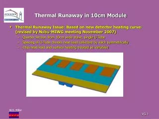
Loads on the 5 K shield lead to increase on static not the same MLI! • provide thermal intercepts • on the many penetrations! • couplers x 8 (9) • leads • cables • Shield surface provides • surface for thermal • strapping with small braids From Webex SCRF meeting on 5 K shield removal TTF module thermal modeling
5 K shield removal: what happens @ 2K? • From Tom Cryo spreadsheet (Feb07) • 2K: 11.4 (1.7 s + 9.7 d) @ 700 W/W • 5K: 15.0 (10.6 s + 4.4 d) @ 200 W/W • 40K: 153.5 (59.2 s + 94.3 d) @ 16 W/W • Sum 14.4 kW plug power for each module (no overcapacity) • If all 5K load goes into 2K “as is” • Plug power increased by 56% • Need to provide same efficient radiation shield for the 2K mass, with at least 10 layers MLI protecting the 2K cold mass • If only radiation flow into 2K (consider factor 2 increase for worse MLI protection) and all conduction intercepted • Plug power increased by 15% • 5K thermalization for 3 posts, 8-9 couplers, HOM, leads, cables From Webex SCRF meeting on 5 K shield removal TTF module thermal modeling
Operation vs Capital • Range of effect on plug power (operation cost) is 15% to 55% without redesigning cross section • optimistic conditions given the many penetrations that the module has to the 2 K environment, and located at different positions along the transverse section (support at top, couplers to the side) • Bulky braids? • We need anyway a 5K cryo circuit for 90% of the conduction heat removal From Webex SCRF meeting on 5 K shield removal TTF module thermal modeling
From Webex SCRF meeting on 5 K shield removal 5 K thermal anchors in TTF 5 K shield surface provides convenient thermalization using small braids TTF module thermal modeling
Type I--III • “Historical” note: One of the most effective cost reduction stategies from generation I to generation II was the elimination of the many braids to perform the shield thermalization • Sometimes changes that seem minor have heavy implications later in terms of complexity or cost • e.g. discussions yesterday/today of modules plug compatibility between regions • changes in the shield geometry from TypeII+ to XFEL proto TTF module thermal modeling
Example: Type III+ modification Small change to eliminate interferences Seems minor, but it complicates life and adds manifacturing stages (in/out rolling machine) price up, estimate amounts to 5-7% TTF module thermal modeling
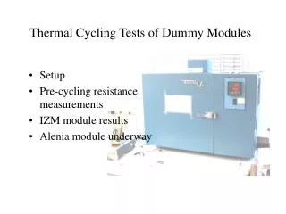
TTF Thermal analysis with ANSYS • We did transient thermal analysis 12 years ago on shields only • Serena developed an ANSYS model for static and transient thermal behavior aimed at • static and transient heat loads, • thermal gradients on the internals during transient, … • comparison of different cooling procedures • Opportunity to benchmark with present M3* testing at CMTB • The input data (cool down times, flow rates, …) • from CMTB cryogenic system • Several cooldowns available • A new set of thermal sensor has been included in CMTB TTF module thermal modeling
Model overview TTF module thermal modeling
Thermal conditions • In the simulation (both static and transient) we have implemented the following thermal conditions: • Cooling provided by convection at the finned Aluminum tubes integrated in both the 5 K and 70 K shields • Conduction through penetration and supports (posts, couplers) • Thermal radiation load • 300 K thermal boundary at top of posts • Under development: still working on or planning • Model so far has double shield and no radiation load at 2 K • No single shield model • Details of cavity tanks are still missing • Imposed temperature at the GRP and connections to tanks TTF module thermal modeling
Heat conditions in the transient analysis • Time dependent convection cooling at the 5 K and 70 K finned tubes and HeGRP • Linear T decrease • Evaluation of hf from fluid • Imposed linear temperature decrease at the 2 K cavity boundary, with no limit to heat exchange • Time dependent heat loads: • Radiation heat flux acting on the shields surfaces • Conduction effects from couplers being implemented at 70 K, 5 K and 2K • not modeling real coupler geometry, though • heat load at the thermal anchors positions on the shields TTF module thermal modeling
Convective heat exchange on 70 K pipe Derived from fluid properties (T, P, …) and mass flows TTF module thermal modeling
Cooldown rates (linear) 70 K 5 K 2 K Simplified model presented at Sendai, simple linear loads TTF module thermal modeling
Radiation load through MLI • CERN data used so far • From r.t. to neglibible temperatures using 30 layers MLI • 1 W/m2 • From 80 K to neglibible temperatures using 10 layers MLI • 0.05 W/m2 • Scale behavior during cooldown from these data usingexperimental plots reported in J. Weisend text From J.Weisend TTF module thermal modeling
Heat flow on 70 K pipe during cooldown Simplified model presented at Sendai, simple linear loads TTF module thermal modeling
Gradient on 70 K shield Simplified model presented at Sendai, simple linear loads TTF module thermal modeling
Work still in progress… • Further implementation of heat load sources and complexity of loading conditions • Using CMTB cooldown data • Getting CMTB data from DESY to be analyzed • provides model benchmark • TO DO: Structural analysis at maximum gradients • mechanical interferences • Model can be extended for exploring different cooldown procedures or thermal intercept strategies • Big help from W. Maschmann, K. Jensch, R. Lange TTF module thermal modeling
Measured data at CMTB – outer shield TTF module thermal modeling
Measured data at CMTB – inner shield TTF module thermal modeling
Shield radiation CERN Data on MLI Scaled using T1^4-T2^4 TTF module thermal modeling
Conduction at couplers Tesla TDR Data for stationary operation Scaled with cryocomp data for Kt TTF module thermal modeling
Fluid parameters, 2 K circuit TTF module thermal modeling
Fluid parameters, 5 K circuit TTF module thermal modeling
Fluid parameters, 70 K circuits TTF module thermal modeling
Results with CMTB cooldown – 70 K TTF module thermal modeling
Results with CMTB cooldown – 5 K TTF module thermal modeling
Loads TTF module thermal modeling
Detail of inner shield TTF module thermal modeling
Position of coupler load on model TTF module thermal modeling