Download
1 / 20
200 likes | 456 Views
CAUSES AND LESSONS OF THE 20 NOVEMBER 2003 GEOMAGNETIC SUPERSTORM. V . Grechnev , A . Uralov , G.Rudenko, I.Myshyakov, V.Fainshtein, Ya.Egorov, A.Afanasyev ( Institute of Solar-Terr. Phys., Irkutsk, Russia ) V.Slemzin ( Lebedev Physical Institute FIAN, Moscow, Russia )

E N D
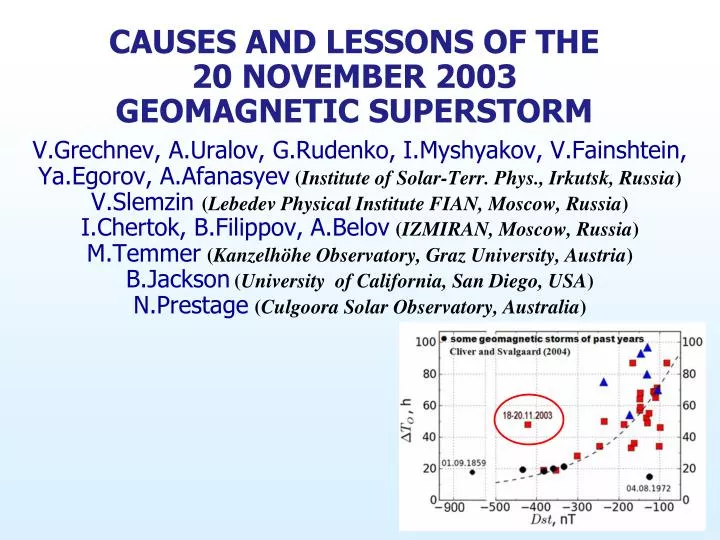
CAUSES AND LESSONS OF THE 20 NOVEMBER 2003 GEOMAGNETIC SUPERSTORM V.Grechnev, A.Uralov, G.Rudenko, I.Myshyakov, V.Fainshtein, Ya.Egorov, A.Afanasyev(Institute of Solar-Terr. Phys., Irkutsk, Russia) V.Slemzin (Lebedev Physical Institute FIAN, Moscow, Russia) I.Chertok, B.Filippov, A.Belov(IZMIRAN, Moscow, Russia) M.Temmer(Kanzelhöhe Observatory, Graz University, Austria) B.Jackson(University of California, San Diego, USA) N.Prestage(Culgoora Solar Observatory, Australia)
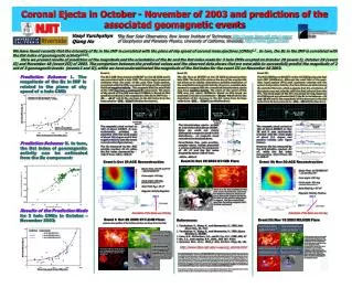
Chertok et al. 2013, Sol. Phys. 282, 175 r 0.67 18–20.11.2003 Magnetic flux in source region, 1020Mx 18–20.11.2003 Event: Challenges & Significance • Moderate 18.11.2003 solar eruptive event… • …caused the 20.11.2003 geomagnetic storm, most severe in almost quarter a century • Relations between parameters of the event and its geomagnetic outcome deviate from all known correlations • Hazards of geomagnetic storms for industrial systems urge one to find out causes of extreme geomagnetic effect of this event • We search for causes of the 20.11.2003 superstorm by comparingwith extreme 2829.10.2003 event of preceding rotation of this activity complex (in different AR)
Several Papers Addressed Enigmatic 18–20.11.2003 Geoeffective Event: Gopalswamy, Yashiro, Michaleket al. (2005, GRL 32, L12S09) Yurchyshyn, Hu, and Abramenko (2005, Space Weather 3, S08C02) Yermolaev, Zeleny, Zastenker et al. (2005, Geomag. Aeron. 45, 20) Ivanov, Romashets, Kharshiladze (2006, Geomag. Aeron. 46, 275) Möstl, Miklenic, Farrugia et al. (2008, Ann. Geophys. 26, 3139) Srivastava, Mathew, Louis, Wiegelmann (2009, JGR 114, A03107) Chandra,Pariat, Schmiederet al. (2010, Solar Phys. 261, 127) Kumar, Manoharan, and Uddin (2011, Solar Phys. 271, 149) Lui (2011, Space Sci. Rev. 158, 43) Marubashi, Cho, Kimet al. (2012, JGR 117, A01101) Cerrato, Saiz, Cidet al. (2012, J. Atm. Sol.-Terr. Phys. 80, 111) – assumed (i) ‘simple’ eruption and (ii) correspondence of magnetic cloud and pre-eruption structure in handedness However, there is no satisfactory explanation to: Strongest field in magnetic cloud (MC) Different helicity signs in MC and its presumed solar source Differentdirections of the magnetic field in MC and its source (>90) Particularities of CME – see further
Two CMEs:CME1 andhalo CME2 Most studies associate magnetic cloud with eruptive filament and CME2 However: “halo” was a shock trace, while CME2 was not Earth-directed Shock CMEs • Halo: shock trace • CME2 body: expanding arcade • Core not visible
Filament eruption and CME2 • Filament eruption inH line • Filaments and CME2 are similar in direction and shape • However, CORONAS-F/SPIRIT (304 Å):filament has not left Sun but transformed into Y-like cloud: • Filament and “Y” similar in kinematics and masses; • CME2 was coreless. • Grechnev, Chertok, Slemzin et al. (2005, JGR 110, A09S07): “filament failed to become a CME core”.
Comparison of 28–29.10.2003 and 18–20.11.2003 events Moderate Forbush decrease with strong magnetic field small size of magnetic cloud (MC) Strong field B with ordinary magnetic flux = B A small cross section Aof MC Confirmed by three reconstructions of MC, e.g.:
MCs on 29 October and 20 Novemberin the same scale Reconstructions of MC cross sections from ACE data (Yurchyshyn et al., 2005)
Where were the boundaries of near-Earth magnetic cloud? • Usually MC is considered as a ‘cold magnetic reservoir’. Its boundaries are traditionally determined by the conditions: • < 1 • Smooth rotation of magnetic field • Lowproton temperature • Axial field has constant direction • Not all of these were the case in 20.11.2003 MC: • Proton temperature varied within a wide range • Not everywhere << 1 • Axial field changed direction
ACE Interplanetary Data Regions Bz >0 (A &C) belong to MC These regions neglected previously indicate disconnection of MC from the Sun Linear velocity profile self-similar expansion; compensation for expansion produces ‘snapshot’ of MC • Solid vertical line:shock front • Dashed vertical line: sharp density increase of suprathermal electrons in both directions – MC boundary • Bz > 0in regionsA,C:regular continuation of region B
‘Snapshot’ of MC from ACE Data Variations of Bcomponents correspond to pass of spheromak; Bzchanged sign twice MC size ≈ 0.2 AU Balansof Bztotal magnetic fluxes in regionsB (6.21020Mx) andA+C (+5.21020Mx) Cf. Ivanov & Kharshiladze (1985, Solar Phys. 98, 379)
Neither ICME1 nor ICME2met Earth and could cause superstorm Expansion angle of spheromak SGS 14 3-D Reconstructions of Heliospheric Density Distribution from SMEI Data 29 October: typical flux rope 20 November:compact ICME different from a torus perpendicular to eclipticplane spheromak
Disconnection from Sun Orientations of CME1 and CME2 estimated from ice-cream cone model Spheromak expanded indense tails of CME1 and CME2 being restricted laterally Magnetic field in spheromak 20% higher than in flux rope with the same surface pressure Sun Earth CME2 CME1 Weak Expansion of Spheromak
Causes of Superstorm • Weak expansion of disconnected spheromak (within cone 14) +magnetic flux conservation strong field in spheromak • Almost exactly southward orientation of the magnetic field vector in MC: negative Bz0.8|В| • Central impact of MC on Earth’s magnetosphere • To meet Earth with expansion angle 14, CME should be launched near solar disk center • LASCO could not detect it: appearance in C2 field of view at r > 16R– scattered light meager • Support from different observations
Initial size of CME:ring structure near solar disk center in SXIimages Aparentexpansion in SXI images corresponds to frequency drift of type IVburst Final speed of radial expansion100 km/s, average MC speed 865 km/s angle 14 Dynamic Radio Spectrum and GOES/SXI Images • Type II bursts: traces of shock waves • Low-frequency envelope of type IVburst – plasma frequency in expanding volume: n 1/r3, fp n½
Null point N S S N N S Direction of eruption Reason for Transformation of Erptive Filament into Y-like Cloud • Pass of eruptive filament through null point of coronal magnetic field • Orientations of fields allow reconnection of filament only with west section of quadrupole,a dipole “bridge” • Subsequent formation of spheromak in interaction between magnetic fields of filament and dipole bridge
Reconnection and Formation of Right-handed Spheromak N AR503 t6 t3 t1 t2 S N S t4 t7 t8 Y Y Torus moving up stretches bridge. Reconnection between legs of bridge and its forced eruption Collision of left-handed filament with dipole bridge Filament contacts itself, reconnection, two tongues of Y-like cloud form Right-handedpair oflinked toriforms t5 Field lines of vertical torus scatter along horizontal one. Then pair of linked tori evolves into spheromak Filament portion “attached” to bridge disconnects to form a torus
Probable Solar Source Region: EIT 195 Å andExtrapolation from MDI Magnetogram Development of dimming in AR 503 and southward indicates eruption of dipole bridge Magnetic field in erupted dipole directed almost exactly south (80), which corresponds to MC and opposite to axial field of filament Magnetic flux in bases of erupted bridge (dimmings) at a height of 30 Mm (~111020Mx) is close to estimated one in magnetic cloud (5.51020Mx,Möstl et al., 2008) and sufficient to provide strong field actually observed near Earth
Particularities of the Event. Results and Consequences • Anomalous eruption: mass dispersal over large area due to reconnection between magnetic field in filament and corona. • Outer halo of fast CME was a shock trace and did not indicate its earthward direction. • Radio burstsreflected in detail eruptive processes and presented kinematics of eruptive structures and shock waves. • CME solar source region presented comprehensive information about magnetic cloud, however: • Helicity sign of magnetic cloud might not correspond to own helicity of pre-eruption structure. • Conception of magnetic cloud as a cold flux rope is not universal. • Atypically weakICME expansion increases geomagnetic effect. This study is presented in four companion papers “A Challenging Solar Eruptive Event of 18 November 2003 and the Causes of the 20 November Geomagnetic Superstorm” (Solar Physics).
Morphological Reason for Transformation of Eruptive Filament into Y-like Cloud Filament is attached to its inversion line Change in connectivity of inversion lines Br(h)at a height of 140 Mm