Download

1 / 55
550 likes | 699 Views
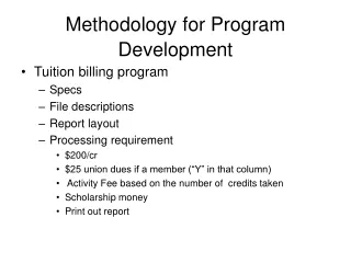
Development of a Seismic Design Methodology for Precast Floor Diaphragms. Robert Fleischman and Ge Wan, UA Clay Naito, Richard Sause and Liling Cao, LU Jose Restrepo and Matt Schoettler , UCSD S.K. Ghosh, S.K. Ghosh Associates, Inc. Physical Scope Prototype Structure Design. HISTORY:.

E N D
Development of a Seismic Design Methodology for Precast Floor Diaphragms Robert Fleischman and Ge Wan, UA Clay Naito, Richard Sause and Liling Cao, LU Jose Restrepo and Matt Schoettler, UCSD S.K. Ghosh, S.K. Ghosh Associates, Inc.
Physical Scope Prototype Structure Design HISTORY: • Design • Design for • Design for untopped and topped systems • Design for different diaphragm details
Physical Scope Prototype Structure Design Design of prototype structures: • Design for different seismic locations • Design for different possible LFR systems • Design for untopped and topped systems • Design for different diaphragm details
Physical Scope Prototype Structure Design Seismic zones provided by S.K. Ghosh
Physical Scope Prototype Structure Design Ground motions at selected locations
PS#1: 4-story side-by-side parking garage PS#2: 4-story helical parking garage Perimeter shear walls Distributed shear walls PS#5: two-way moment frame parking deck Ramp PS#3: 5-story L-wing office building PS#4: 4-story office building/school Central core Distributed cores Physical ScopePrototype Structure Design
Physical Scope Prototype Structure Design Seismic design of PS#1: Vertical distribution: Design Code IBC 2003 Ss 0.58 S1 0.147 Soil Site Class C Fa 1.17 Fv 1.65 Sms= Fa Ss 0.68 Sm1= Fv S1 0.24 SDS= 2/3 Sms 0.45 SD1= 2/3 Sm1 0.16 EW Shear Walls R=5, W0=2.5, Cd=4.5 NS Light Framed Walls R=4.5, W0=2.5, Cd=4 Seismic Design Category C Cs 0.09 Cs,min 0.0198 Cs,max 0.0589 Base shear 1470 kips Diaphragm design:
Physical Scope Prototype Structure Design Evaluate the effect of possible LFR layouts for moderate zones. Evaluate the effect of possible LFR layouts for high zones. * Evaluate topped systems for moderate zones. *Evaluate untopped systems for high zones. Evaluate topped and untopped systems for near field. Evaluate topped and untopped systems for soft soil sites. Prototype structure design matrix (Parking Garage)
Physical Scope Representative Details We need two sets of representative details, untopped and topped, which are uncoupled from the moderate and high seismic zones. • Chord steel reinforcement • Diaphragm shear reinforcement • Wall anchorage (Shear walls & lite walls) • DT-to-Spandrel connections • DT-to-IT connections • Spandrel-to-Column connections
Physical Scope Prototype Structure Design previous tests • Design • Design for • Design for untopped and topped systems • Design for different diaphragm details
Nonlinear spring and contact elements in ANSYS Properties based on test data of details Analytical Program:Diaphragm FE Model Model of Diaphragm: 2D FE model: PS#1
Physical Scope Representative Details Chord steel reinforcement (untopped-dry) Detail Modeling Test See chord in topping/pour strip. LU test “B” Dry chord detail in PS#1
Physical Scope Representative Details Chord steel reinforcement (topped/pour strip) Detail Modeling Test LU test “F” Pour strip chord detail in Roper An empirical bond-slip stress model (Alsiwat and Saatciogu, 1992)
Physical Scope Representative Details Diaphragm shear reinforcement (untopped) Detail Plate w/ 2 straight bars JVI Hairpin Plate w/ 2 bars at 450 Test Oliva’s test (1999) Test data from UWM or LU. LU test “A” LU test “B” Modeling To be shown later.
Physical Scope Representative Details Diaphragm shear reinforcement (topped-composite) Cover plate connector + wwf Detail Hairpin + wwf Test LU test “D” LU test “C”
Physical Scope Representative Details Diaphragm shear reinforcement (topped: non-composite) Modeling Test An empirical bond-slip stress model (Alsiwat and Saatciogu, 1992) LU test “E” (wwf)
Unity Ratio at 0.1g This plot shows the ratio of shear to tension in the web reinforcement. This plot shows how these forces combine to produce yielding. Analytical Program: Diaphragm Capacity To adequately model the nonlinear behavior of the diaphragm, the combined shear and tension on the web reinforcement must be captured.
Analytical Program Update on Diaphragm Sensitivity Studies Contact Element Modeling of coupled shear and tension behavior: A truss spring model Plastic link elements to match MT test Nonlinear shear spring to supplement shear strength
Analytical Program Update on Diaphragm Sensitivity Studies Modeling of coupled shear and tension behavior: Comparison with Oliva’s test results (1999)
Analytical Program:Sensitivity Studies Secondary Details: PS#1 46 22 32 210 20 22 70 18 22 22
Physical Scope Representative Details Shear wall anchorage (Untopped-dry) Detail Modeling Test One side of a shear connector. (i.e. double stiffness) Lite wall anchorage (Brickstone) LU test “D” Q: Is untopped dry construction used for shear wall anchorage? (Not found in prototype structures, shown below is the lite wall anchorage in Brickstone.)
Physical Scope Representative Details Shear wall anchorage (Topped/pour strip) Detail Test Subtract Weld plate (PS#2) LU test “D” LU test “E” One side of a shear connector. (i.e. double stiffness) Modeling
Physical Scope Representative Details Lite wall anchorage (Untopped-dry) Detail Test subtract Lite wall anchorage (PS#1) LU test “D” LU test “E”
Physical Scope Representative Details Lite wall anchorage (Topped-pour strip) Lite wall anchorage detail in PS#4 (Suitt) Same as Roper shear wall anchorage. Lite wall anchorage detail in PS#2 (Roper) Same as shear wall anchorage other than the bars are at 450.
Physical Scope Representative Details DT-to-Spandrel connections (Untopped-dry) Similar to the lite wall anchorage detail in Brickstone. DT-to-Load bearing spandrel DT-to-Non load bearing spandrel DT-to-Spandrel connections in PS#1 (Brickstone)
Physical Scope Representative Details DT-to-Spandrel connections (Topped, pour strip) Similar to the shear wall anchorage detail in Roper. See slide 15. DT-to-Load bearing spandrel detail in PS#4 (Suitt) DT-to-Non load bearing spandrel detail in PS#2 (Roper) Q:All the DT-to-Shear wall, DT-to-Lite wall and DT-to-Spandrel connections are very similar in the prototype structures. If there is not big difference in the dry detail and the pour strip, topped detail, we may only consider one representative detail: weld plate with straight bars.
Physical Scope Representative Details DT-to-IT connections (Untopped-dry) One side of test “D” i.e. ½ of the flexibility DT-to-IT connection in PS#1 (Brickstone) LU test “B” without end anchor plates (#5 bars)
Physical Scope Representative Details DT-to-IT connections (Topped, pour strip) One side of test “D” i.e. ½ of the flexibility LU test “D” (cover plate connector + 610 W2.9W4) DT-to-IT connection in PS#4 (Suitt)
Physical Scope Representative Details Spandrel-to-Column connections (Untopped and Topped) Do test data available. Need some information about stiffness and strength. Elevation Plan Spandrel-to- Column connection in PS#1
Analytical Program Update on Diaphragm Sensitivity Studies Updated diaphragm sensitivity studies of PS#1: • Effect of seam connections • Typical seam connections • Ductile seam connections • Strong seam connections • Effect of ramp • Effect of ramp walls
Analytical Program Update on Diaphragm Sensitivity Studies Actual strength Double stiffness of a shear connector (one side) Typical Ductile Strong Seam studies Assumptions: 2D inplane FE diaphragm model with cavity: STRESS NO LITE WALL Spandrel effect ignored Diaphragm shear connector behavior based on Oliva’s test data Seam connections assumed to be typical, ductile and strong
Analytical Program Update on Diaphragm Sensitivity Studies Seam studies – Typical seam connection WV Wb
Analytical Program Update on Diaphragm Sensitivity Studies Seam studies – Typical seam connection Response of the inner seam connection in local and global coordinates
Analytical Program Update on Diaphragm Sensitivity Studies Seam studies – Typical seam connection
Analytical Program Update on Diaphragm Sensitivity Studies Seam studies – Typical seam connection Shear response of the middle shear connector along landing end
Analytical Program Update on Diaphragm Sensitivity Studies Seam studies – Typical seam connection Separation of flexural deformation and shear deformation Deflected shapes of the leading subdiaphragm at the last 5 converged load steps
Analytical Program Update on Diaphragm Sensitivity Studies Chord yields Seam studies – Typical seam connection Shear and tension deformation status of the connections at POINT E (0.219g) Web-conn dv : Web-conn dT : Seam-conn dv : Seam-conn dT :
Analytical Program Update on Diaphragm Sensitivity Studies Seam studies – Ductile seam connection WV Wb
Analytical Program Update on Diaphragm Sensitivity Studies Seam studies – Ductile seam connection B: Chord yield
Analytical Program Update on Diaphragm Sensitivity Studies Descending branch Seam studies – Ductile seam connection Shear and tension deformation status of the connections at A (0.22g) Web-conn dv : Web-conn dT : Seam-conn dv : Seam-conn dT :
Analytical Program Update on Diaphragm Sensitivity Studies High deformation demands in seam connections Chord yield Softening of connectors Seam studies – Ductile seam connection Shear and tension deformation status of the connections at B (chord yields) Web-conn dv : Web-conn dT : Seam-conn dv : Seam-conn dT :
Analytical Program Update on Diaphragm Sensitivity Studies Shear deformation limit Shear strength limit Seam studies – Ductile seam connection Shear and tension deformation status of the connections at C (Failure) Web-conn dv : Web-conn dT : Seam-conn dv : Seam-conn dT :
Analytical Program Update on Diaphragm Sensitivity Studies Deformed shape at D A: Failure of landing end B: Failure of 2nd landing joint C: Failure of 3rd landing joint D: Failure of interface Seam studies – Strong seam connection D C B A WV Wb
Analytical Program Update on Diaphragm Sensitivity Studies Shear deformation limit Shear strength limit Seam studies – Strong seam connection Shear and tension deformation status of the connections at D (Failure) Web-conn dv : D C B A Web-conn dT :
Analytical Program Update on Diaphragm Sensitivity Studies Seam studies – Comparison Preliminary Conclusions: D C • For typical design, seam connections will fail first. • Strong seam connections will transfer some of the inertia force of the leading flat to the landing. The landing end becomes the critical joint. • Ductile seam connections protect the landing joints. B A WV Wb
Analytical Program Update on Diaphragm Sensitivity Studies 2. Effect of ramps Assumptions: typical web/seam • 3D 2-story FE model with ramps • Spandrel effect ignored • Diaphragm shear connector behavior based on Oliva’s test data • Seam connections assumed to be one side of a shear connector Diaphragm shear connector Seam connection
Analytical Program Update on Diaphragm Sensitivity Studies Ramp 2. Effect of ramps (no wall) 3rd floor flat C A B Fails at A Fails at B Fails at C
Analytical Program Update on Diaphragm Sensitivity Studies 2. Effect of ramps Shear deformation status of the 3rd floor connections at C (Failure) Web-conn dv : Fails at A Fails at B Fails at C Seam-conn dv :
Analytical Program Update on Diaphragm Sensitivity Studies 2. Effect of ramps Tension deformation status of the 3rd floor connections at C (Failure) Web-conn dT : Fails at A Fails at B Fails at C Seam-conn dT :
Analytical Program Update on Diaphragm Sensitivity Studies 2. Effect of ramps Comparison of force combinations at critical sections with the 2D model without ramp: 3rd floor flat of the 3D model with ramp 2D inplane model without ramp • Compared to the 2D model without ramp: • Leading seams are in higher shear demands. • The landing end and the seam without ramp coming in at roof level become more critical. • Other landing regions and seams are not in higher demands due to the ramp inertia force because of the less inertia from the trailing subdiaphragm.