Download
1 / 26
260 likes | 406 Views
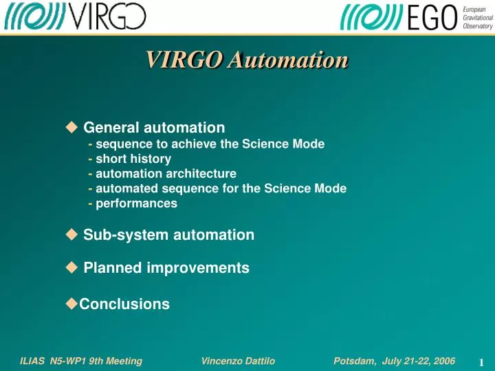
VIRGO Automation General automation - sequence to achieve the Science Mode - short history - automation architecture - automated sequence for the Science Mode - performances Sub-system automation Planned improvements Conclusions.

E N D
VIRGO Automation • General automation - sequence to achieve the Science Mode - short history - automation architecture - automated sequence for the Science Mode - performances • Sub-system automation • Planned improvements • Conclusions ILIAS N5-WP1 9th MeetingVincenzo Dattilo Potsdam, July 21-22, 2006
Schematic sequence to achieve the Science Mode All sub-systems in standard state Initialization Pre-alignment* Locking / Alignment Noise reduction unlock watch Permanent lines injection Science Mode * Skipped when not needed
Schematic sequence to achieve the Science Mode The whole sequence requires hundreds of actions to be performed on the digital control loops: • Control loops closing/opening • Set-points change • Loop gains change • Error signal change • Control filters change • Correction signals change • Global Control state transitions • Related checks
Schematic sequence to achieve the Science Mode • Most of the ITF control loops have real-time feature and belong to the sub-systems. They run on dedicated PowerPC-based CPUs boards (RIO) or custom DSP boards. Servers running on the RIOs provide also the control/command interface. • Commands can be sent to the servers via the VIRGO inter-processes comunication Cm protocol.
? ? Short history 1/2 Up to the commissioning run C4 (June 04) the automation was not implemented and the sequence was manually executed: Cm commands sent to the servers using dedicated GUIs, checks based on the visual inspection of relevant signals and GUIs . DAQ DataDisplays Sub-systems servers GUIs actions ( 2 or more people ) DSPs Slowdown and risk of human errors …
Short history 2/2 Since mid 2004, an activity on automation has been under way. The developed system takes care of sending Cm commands to the servers, of performing the checks and allows the direct implementation of low-frequency control loops. General Automation DAQ Sub-systems servers actions DSPs
AlpLock AlpAli AlpDet AlpCa AlpSa AlpInj Architecture 1/4 The software developed has a server architecture and is named ALP. The basic concept is to use the data acquired by the DAQ and to compute on a standard workstation the state of any subsystem by processing the collected channels related to it. According to the subsystem state, actions can be performed using Cm commands. DAQ AlpMain (master) actions Sub-systems servers actions DSPs
Architecture 2/4 • The ALP server uses the DAQ framework to access the data and to report on the performed actions. • It uses the macro concept to define a set of code related to the same automation phase and a script language to define the macro’s content. • Inside one macro, several functionalities can be used: -ALP variables declaration -DAQ channel properties can be computed in the time domain (mean, min, max, rms, abs) or in the frequency domain (FFT, bandRMS, COHE, …) and stored as ALP variables -Arithmetic operations (+,-,*,/) between ALP variables -test and loop conditions on ALP variables - ALP variables can be sent to the DAQ as new channels -commands can be sent to act on given sub-system servers or other ALP servers -direct call of a macro • Using a set of macros, one can easily define any automation procedure. • In order to better distribute the computational load and to provide a clear hierarchical organization (sub-system-linked) to the different automation tasks, an architecture based on several ALP servers has been defined.
Architecture 3/4 Macro example (abbreviated version of the real macro) MACRO "LOCK_STEP_01" #---Check LOCK_STEP_STATUS. IF LOCK_STEP_STATUS != 0 PRINT_ERROR "WRONG SEQUENCE! It is not possible to move to Step 1 from step " -d LOCK_STEP_STATUS RETURN ENDIF OP LOCK_STEP_STATUS = 0.5 #--- Change B2_3f_Lo demod phase. CMD_CM Lo30 Delay -text B2_3f_Lo -d -40 #---Enable Gc corrections (disabled in Init for safety reasons). CMD_CM Sa_EServerDSP_BS ChangeGain -i 2 -text LockOn -f 1 CMD_CM Sa_EServerDSP_NE ChangeGain -i 2 -text LockOn -f 1 CMD_CM Sa_EServerDSP_WE ChangeGain -i 2 -text LockOn -f 1 #---Set the starting on-fly values for the Gc algorithm. CMD_CM Su_Gc_Partition_Gc GCVSUC_OnflyByName -t "Sensing" -t "Locking_Half_DoubleLoop" -t "Fringe_Offset" -d 0.501 -t "Gain_Mich" -d 8.0 -t "Gain_Prcl" -d 35 -t "Gain_Darm" -d -5e-10 #---Wait for MC mirror to reach low-noise state. OP MC_LowNoise_TARGET = 0.05 EXEC_MACRO MC_LowNoise_AwaitTransition #---Place Gc in "Steady" state. CMD_CM Su_Gc_Partition_Gc GCVSUC_SteerLocking -t Steady WAIT 4
#---Wait until lock is acquired. OP COUNT = 0 OP COUNT_TOTAL = 0 WHILE COUNT < TH_MIN_COUNT && COUNT_TOTAL < 60 OP_CH B7_DC = Min 1. Pr_B7_DC OP_CH B8_DC = Min 1. Pr_B8_DC IF B7_DC < 1.0 || B8_DC < 1.0 OP COUNT = 0 PRINT_INFO "ITF not locked after " -d COUNT_TOTAL -t " seconds," -d B7_NORM -t " " -d B8_NORM ELSE OP COUNT = COUNT + 1 PRINT_INFO "ITF locked for " -d COUNT -t " seconds," -d B7_NORM -t " " -d B8_NORM ENDIF OP COUNT_TOTAL = COUNT_TOTAL + 1 DONE IF COUNT == TH_MIN_COUNT PRINT_INFO "********* ITF LLLOOOCCCKKKEEEDDD ********" OP LOCKED = 1 ELSE PRINT_WARNING "LOCK_STEP 01 ABORTED due to the impossibility to lock after 1 minute" OP LOCK_STEP_RQST = 0 RETURN_LOAD LOCK_LOOP ENDIF #---1.10 Check GC OnFly values. OP GcOnFly_TARGET = 0.501 EXEC_MACRO GcOnFly_AwaitTransition OP LOCK_STEP_STATUS = 1 PRINT_INFO "********************* LOCK STEP 1 CONCLUDED ********************" PRINT_INFO "********************* Dark Fringe: 0.50 ********************" STATE "LockStep01 OK" ENDMACRO
Automated sequence for the Science Mode 1/5 All sub-systems in standard state Initialization Pre-alignment* Locking / Alignment Noise reduction unlock watch Permanent lines injection Science Mode * Skipped when not needed
Automated sequence for the Science Mode 2/5 Pre-alignment sequence This sequence, not always executed at each lock acquisition attempt, is implemented by the following three macros: • “Direct_Beam_Alignment”: Alignment of the direct beam into the North and the West arms. • “Cavities_Alignment”: North and West arm cavities independent locking, their non-linear alignment (when really needed) and their linear alignment. • “PR_Coarse_Alignment”: Non-linear alignment of the PR mirror, with respect to the arm cavities mirror alignment performed in the previous macro.
Automated sequence for the Science Mode 3/5 Locking/Alignment/NoiseReduction/LinesInj. sequence • For the ITF locking a novel strategy, called Variable Finesse Lockinghas been adopted; • Basic Idea: the ITF is locked on the half (grey) fringe, then brought sequentially to the dark fringe through several steps. During those steps the control scheme is changed. • The sequence is implemented by a single macro, named “Lock_Step_request” (C7 case): • STEP 1 : Lock acquired with the PR mirror misaligned by 10 mrads and the ITF on the grey fringe (i.e. Dark Fringe at 50%) • STEP 2 : A boost filter added to the PRCL and MICH loops. Dark Fringe from 50 to 40%. • STEP 3 : CARM loop controlled by the SSFS. • STEP 4 : PR mirror aligned and consequently the power stored in the ITF increases
Automated sequence for the Science Mode 4/5 Locking/Alignment/NoiseReduction/LinesInj. sequence • STEP 5 : Dark Fringe from 40 to 20%. A boost filter added to DARM loop. • STEP 6 : Dark Fringe from 20 to 8%. • STEP 7 : Dark Fringe from 8 to 5%. • STEP 8 : Final step to Dark Fringe. Transition of the MICH loop error signal from the B1p DC signal to the B5 demodulated. Angular drift control switched on. • STEP 9 : Transition of DARM loop error signal from the noisy B8 to the less noisy B1p demodulated. • STEP 10 : Output Mode Cleaner (OMC) put on resonance, transition of DARM loop error signal from B1p to B1. After the transition all the noisy mirror motion dampers are switched off. • STEP 11 : A filter having a reduced band and a high roll-off is added to the MICH loop. • STEP 12 : Activation of the tidal control, force re-allocation on marionette, swapping to low-noise coil drivers. • STEP 13 : Re-adjustment of demodulation phase and gain of PRCL loop. • STEP 14 : A fraction of the MICH correction signal is sent in counter-phase to the end mirrors. • STEP 15 : Permanent lines are added to the different mirror corrections for ITF calibration.
Automated sequence for the Science Mode 5/5 Unlock watch During the sequence execution and after its completion, a special macro (named Lock_Guard), working in the background, watches for any unlock event. In case of an unlock, it brings the ITF to the lock acquisition pre-conditions (it launches the Init macro), also avoiding over-excitation of the sub-systems.
Automation client overview Server status Server / process name (command menu) The most recent messages generated by all the servers User info To access the last part of the log-file
Automation client Command menu Server / process status
Automation client Dialog box Server / process status
Noise reduction Alignment Lock to DF (variable finesse) Unlock watch 5 mins Performances 1/2 • Execution time of the Pre-alignment sequence: ~5’ (may be higher depending on the initial misalignment). • Execution time of the Locking/Alignment/NoiseReduction sequence: ~5’
C7 76 unlocks from science mode Performances 2/2 C6
General automation - sequence to achieve the Science Mode - short history - automation architecture - automated sequence for the Science Mode - performances • Sub-systems automation • Planned improvements • Conclusions
Sub-systems automation • Several types of automation are available at the level of the sub-systems • When real-time features are needed, it has been implemented at level of DSPs. A few examples: - auto switch high/low LC gain of MC and IB - automatic switch to low noise MC LC filters • Implemented at level of servers. An example: - auto fine/coarse transition of LC, done by Galaxie server • When the speed is less critical, it has been implemented at level of sub-system ALP servers. A few examples: - background watch for too much high power on photodiodes and consequent safety action (AlpDet) - MICH and PRCL loops UGF measurement and stabilization (AlpLock) - sensitivity curve measurement (AlpCa) - hundreds of misc. macros called by AlpMain
General automation - sequence to achieve the Science Mode - short history - automation architecture - automated sequence for the Science Mode - performances • Sub-systems automation • Planned improvements • Conclusions
Planned improvements • Monitoring of all Servers status and check of correct handling of the requested commands. • Automated subsystem failure identification and recovery. • Automated recovery of the Science Mode(failure identification, safety actions and recovery included): (It is already possible to leave the ITF locked without any operator in the control room: when the ITF unlocks AlpMain performs a set of safety/init actions but does not try to relock the ITF). The aim is that, once left locked at the end of the shift, in the case of an unlock during the night or the weekend, ALP should manage the situation by : i) attempt to perform a set of pre-defined safety actions, mainly aimed at preventing further excitation or misalignment of the mirrors; ii) identify whether the source of the unlock is due to a problem related to a particular sub-system process - typically a server crash or a server not responding. In this case, ALP attempts to restore the process; iii) try to relock the interferometer, performing the whole automated sequence. • ALP fast: reduce as much as possible the overall execution time of the whole sequence. The achievement of this is based on the optimization of the procedure (sleep time and sequence) and on the possibility to execute, where possible, actions in parallel, relying on the several available Alp servers.
Conclusions A first phase of the automation effort has: -allowed for a short recovery time (typical execution time of the whole procedure is ~10’) following an unlock, thus simplifying and speeding up the daily commissioning activities, where unlocking/relocking the ITF is often required -considerably reduced the risk of human error; -has been an important element in achieving the high duty-cycle during the last two commissioning runs (C6 and C7) - provided a friendly tool allowing the operator to easily, reliably and quickly drive the ITF into the required state A second (and more ambitious) automation phase is planned, to add more intelligence inside, in particular to achieve the Science Mode auto-recovery (failure identification and recovery actions included) So far, more than 10000 lines of scripting (AlpMain plus Alp sub-systems servers) Several persons involved in the Automation activity ( S.Braccini, F.Carbognani, V.Dattilo, M.Evans, G.Hemming, B.Lopez, J.Marque, A.Masserot, E.Tournefier)
extra slides Photodiode Signals Mirror Corrections Locking Frequency: 10 kHz Alignment Frequency: 500 Hz ITF Control