Download
1 / 27
270 likes | 388 Views
Representation and Evolution of Lego-based Assemblies. Authors:. Maxim Peysakhov, Vlada Galinskaya, William C. Regli ( Drexel University). Contacts:. {umpeysak, uvgalins, regli}@mcs.drexel.edu Geometric and Intelligent Computing Lab Department of Math. and Computer Science

E N D
Representation and Evolution of Lego-based Assemblies Authors: Maxim Peysakhov, Vlada Galinskaya, William C. Regli (Drexel University) Contacts: {umpeysak, uvgalins, regli}@mcs.drexel.edu Geometric and Intelligent Computing Lab Department of Math. and Computer Science Korman Computing Center Drexel University Philadelphia, PA 19104 (215) 895-6827 http://edge.mcs.drexel.edu/GICL/
Outline • Outline. • Project goals. • Project statement. • Background. • Genetic Algorithms. • Previous work on Lego and GA. • Approach. • Formulation. • Representation. • Encoding • Operators. • System overview. • Examples. • 10 by 10 by 10 • Pillars • Limitations. • Conclusions. • Contributions. • Future work. • Acknowledgments. • Bibliography.
Project goals • To develop a tool to evolve Lego structures with pre-defined characteristics. • In order to achieve it we needed: • Find a way to represent a Lego assembly precisely and unambiguously. • Encode the Lego assembly as a chromosome. • Adapt genetic operators for this type of chromosome. • Develop the system which performs Genetic optimization on Lego structures.
Project statement • The main contribution of this research is in the application of the GA to the practical task of Lego design generation. • Innovations: • We adapted labeled mechanical assembly graph a representation to a Lego designs. • We developed a graph grammar to define valid combinations of the nodes and edges precisely and unambiguously.
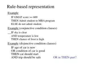
Background: About Genetic Algorithms • In the 1950’s and 1960’s computer scientists started to study the evolutionary optimization systems. Genetic Algorithms were one of them. • Genetic Algorithms (GA) operate on the set (population) of candidate solutions (individuals are also called chromosomes) . • Chromosomes are the strings or arrays of genes (a gene is the smallest building block of the solution). • Each iteration of the search is called a generation. • The idea was to evolve a solution of high quality from the population of candidate solutions. Skip this slide, you know it
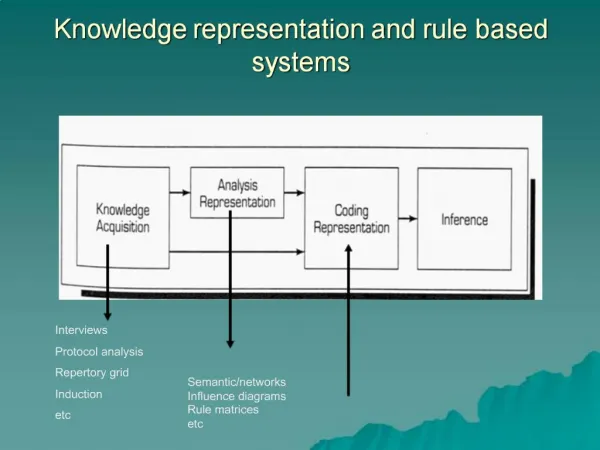
Background: Architecture of the Genetic Algorithm Data Best solution found so fare Initialization Initial Population Evaluate Chromosomes Evaluated Population Next Generation Select Chromosomes Mutate Chromosomes Candidate Next Generation Crossover Chromosomes Candidate Next Generation Skip this slide, you know it
Background: Previous Work on Using GA to Generate Lego Designs • Previous work in this field was done by J. B. Pollack and P. J. Funes, and described at J. B. Pollack, P. J. Funes “Computer Evolution of Buildable Objects.” Fourth European Conference on Artificial Life, P. Husbands and I. Harvey, eds., MIT Press 1997. pp 358-367, 1997. • They used: • Networks of torque propagation to model the behavior of the Lego structure under stress. • Assembly tree representation of the Lego structures. According to authors this representation is one of the limitations of their work. We tried to address this limitation by utilizing assembly Graph representation of the Lego Structures. • Genetic programming operators.
Approach: Problem Formulation • We are considering a limited number of blocks with well-defined connection capabilities modeled from a set of Lego Mindstorms robot kits. • Lego represents a sufficiently complex, multi-disciplinary design domain that includes a wide variety of realistic engineering constraints. • The domain is sufficiently discrete as to be tractable. • Many tools for simulation and testing are readily available. Example of a simple Lego mechanism
Approach: Problem Formalization ThroughLego Grammar. • A graph grammar designed to handle thee-dimensional structures assembled from Lego elements. • The grammar vocabulary is {MECHANISM,Module, Connect,Block, Element, Disk, Pole, PegPair, Snap,Insert,TInsert, GTrans, Beam, Brick, Plate,Wheel, Gear,Axle, PozX, PozY, SizeX, SizeY, Len, Diam, Teeth, Hole (, ), [, ], ;} • Starting word of the grammar is {MECHANISM}. • Terminal words of the grammar are {Snap,Insert,TInsert, GTrans, Beam,Brick, Plate,Battery, Motor,Wheel, Gear,Axle, SizeX, SizeY, Len, PozX, PozY, Diam, Teeth, Hole (, ), [, ], ;}. Terminal words “()[],;” are used only to make sentences easier to read. • Terminals PozX, PozY, SizeX, SizeY, Len, Diam, Hole and Teeth are parameters. PozX {1 .. SizeX } PozY {1 .. SizeY } SizeX {1, 2, 4, 6, 8, 10, 12, 16} SizeY {1, 2, 4, 6, 8, 10, 12, 16} Len {1, 2, 4, 6, 8, 10, 12, 16} Hole {1 .. (Len - 1) } Diam {17, 30, 43} Teeth {8, 16, 24, 40}
Approach: Example of Lego Grammar. • MECHANISM, Module,Element, Block, Disk, Pole,Beam, Brick, Plate,Battery, Motor,Wheel, Gear and Axle are the nodes of the graph grammar. • x N(G), x { Block, Disk, Pole,Beam, Brick, Plate,Battery, Motor,Wheel, Gear,Axle} • Connect, Snap,Insert,TInsert and GTrans are the edges of the graph grammar. • y E(G), y { Snap, Insert, Tinsert,GTrans }
Approach: Representation of Lego Elements • Each Lego element is represented by a labeled node n such that n N(G). • The node label contains the type and the parameters of the element. (For now, our program can operate only with 3 types of Lego elements, namely Beam, Brick, and Plate). • Number and nature of parameters specified in the label depends on the type of the element. (For Beam, Brick, and Plate these parameters are the number of pegs on the element in X and Y dimensions.) Examples of Lego blocks (left) with labeled nodes (right).
Approach: Representation of Lego Connections • Each Lego connection is represented by a labeled edge e such that e E(G). • The edge label contains the type and the parameters of the connection.(For now our program can operate only with one type of Lego connection a Snap Fitsince this is the only possible connection between Brick, Beam and Plate elements). • Snaps are directed edges(arrows pointing from the Block, which provides pegs to the Block thatprovides connection surfaces.) • Label contains a Peg-Pair which is used to define the Pair of corresponding pegs in the connection.[(PozX1,PozY1);(PozX2,PozY2)] Example of the Peg coordinates and Snap connection.
Approach: Representation of Lego Assemblies • Each Lego structure is represented by directed labeled assembly graph G. • Non-empty set N(G) of nodes n, represents Lego elements. • Set E(G) of edges e, representing connections and relations between those elements. Example Lego structure with assembly graph
Approach: Example of an Assembly Graph Example of the assembly graph for the Lego car.
Approach: GA Encoding Scheme • The chromosome is represented by a combination of two data structures: • array containing all nodes N(G) called Genome • adjacency hash table containing all edges E(G) • Key value of the hash table is used to represent function of the graph G, and defines the position and direction of an edge: • Key "1>3" means that the edge is • located between nodes 1 and 3 and • is directed to node number 3. • Key "1>3" is equivalent to key "3<1” Chromosome of the example structure
Approach: Genetic Operator - Initialization • The initial population is generated at random. • First ten nodes of random types are generated with random dimensions. • Then, 9 to 13 edges are generated and placed at random subject to the constraint that the resulting structure must be physically feasible. • In the future we will look into creating and applying initialization rules to promote exploration of specific areas of the fitness landscape.
Approach: Genetic Operator - Mutation • Mutation operator works on the genome array • If the gene is to be modified it is: • Replaced with a random Lego element of the same type. • If some edges became • invalid after the element • was mutated then these • edges are reinitialized at • random. Sample structure with a mutated beam.
Approach: Genetic Operator - Crossover • Crossover is performed with the help of two genetic operators: cut and splice. • The cut operator applied to both chosen chromosomes at independent randomly selected points. • Tail parts of the chromosomes spliced with head parts of the other chromosome. • Chromosome length can vary during the evolution process. Sample structure after Cut operator was applied at the point 3. Head and tail sub-graphs spliced with one random edge.
Approach: Handling Over-specified and Under-specified Chromosomes • Under-specification results in the disjoint assembly graph. (The nodes of the sub-graph containing the 0-th node are selected to be dominant.) • An over-specified chromosome either results in the blocks sharing the same physical space, or are connected by the set of edges, which imply two different locations for the same node. (The node or edge which was assigned the location first is marked as dominant) • The submissive sub-graph • is not deleted from the • chromosome, but is ignored • in most calculations. Example of the blocks sharing same physical space (left) and infeasible connection edges (right).
Approach: Evaluation Functions • Generally evaluation function was created according to the following form: • Where: • ai - the properties of the graph we want to maximize • bi - the properties of the graph we want to minimize • ci - the properties of the graph we want to bring as close as possible to the constant ti • Pi - the wait function. • For most important properties properties of the graph Pi = X • For less important properties properties of the graph Pi = X½ • For least important properties properties of the graph Pi = X¼ ( 1+ Pi(ai) ) ( 1+ Pi(bi) + Pi(|ci - ti|) )
System Overview • Our system was extended from sGA originally created by Prof. Stephen Hartley in 1996 and written on the Java programming language. • Java3D package and VRML97 were used in order to create a visualizer to monitor Lego structures as they evolve. • The system supports: • One-point crossover • Proportional, rank, universal stochastic sampling, sigma scaling, and Boltzman selection techniques • Elitism • And allows input of the mutation and crossover rates and the population size.
Examples: 10 by 10 by 10 Light Structure • In this case the goal was to evolve a structure with the size of 10 Lego units in each x-y-z dimension with the minimal weight. • Left structure was created at 895 generation and has sizes 10 by 10 by 6.8 • Right structure was created at 3367 generation and has sizes 10 by 10 by 10. • Both structures among the lightest possible structures that satisfy these parameters that can be created from the set of elements given.
Examples: Pillar-Like Dense Structure • In this case the goal was to evolve a dense pillar-like structure with the 2 by 4 base and 20, 40 and 60 height. • Structures shown where evolved in 5000 generations on average. • All of them exactly match desired size and among densest possible structures. Height 20, 40 and 60 from right to left
Examples: System Limitations System tends to apply connections to the wrong node types. System not always able to discover a global maximum. Although we used assembly graph to represent Lego structure system tends to evolve structures that can be described by a simple tree or a list. Snap connection used on Axle nodes (top) Insert connection used on two Beams (bottom)
Conclusions: Contribution • We introduced our approach, prototype system and initial experimental results toward the evolution of Lego structures. • The main research contributions described in this paper are the development of a graph based representation scheme for Lego Assemblies and its encoding as an assembly graph for manipulation and evolution by Genetic Algorithms. • Another unique feature of our research is the development of a graph grammar for use in representing Lego assemblies. Although we used it in only to formalize the problem in our documentation we believe that Lego sentences, rather than graph encoded as chromosomes, can bring our system to a new level.
Conclusions: Future Work and Enhancements • More types of Lego elements and connection. • Introducing kinematic chains and evaluation functions to evaluate them. • Creating a mutation operator, which would alter small sub-graphs. • More types of crossover operator. • Using guided initialization. This would mean introducing absolute rules as well as probabilistic rules and applying them during the generation of the initial population.
Bibliography 1. P. Bentley (Editor) Evolutionary Design by Computers. Morgan Kaufmann Publishers; ISBN: 155860605X; 1999 2. S. C. Chase, Representing designs with logic formulations of spatial relations, Workshop Notes, Visual Reasoning and Interaction in Design, June, 1996. 3. D. E. Goldberg, Genetic Algorithms in Search, Optimization and Machine Learning Addison-Wesley Twenty-two points, plus triple-word-score, plus fifty points for using all my letters. Game's over. I'm outta here.Pub Co; ISBN: 0201157675; 1989. 4. M. J. Jakiela: Structural Topology Design with Genetic Algorithms, Computer Methods in Applied Mechanics and Engineering, June, 1998. 5. M. J. Jakiela, D. Wallace, W. C. Flowers, Design search under probabilistic specifications using genetic algorithms, Computer-Aided Design, V 28, N 5, pp. 405-421, 1996. 6. M. J. Jakiela, J. W. Duda, Generation and classification of structural topologies with genetic algorithm specification, Journal of Mechanical Design, V 119, Number 1, March, pp. 127-130, 1997. 7. M. J. Jakiela, C. D. Chapman, K. Saitou, Genetic algorithms as an approach to configuration and topoly design, Journal of Mechanical Design, V 116, December, 1994. 8. E. A. Jones, Genetic design of antennas and electronic circuits, Ph.D. Thesis, Department of Electrical and Computer Engineering Duke University, 1999. 9. J. B. Pollack, P. J. Funes, Computer Evolution of Buildable Objects. Fourth European Conference on Artificial Life, P. Husbands and I. Harvey, eds., MIT Press 1997. pp 358-367, 1997. 10. J. B. Pollack, P. J. Funes, Evolutionary Body Building: Adaptive physical designs for robots. Artificial Life 4, pp. 337-357, 1998. 11. J. B. Pollack, P. J. Funes, Componential Structural Simulator. Brandeis University Department of Computer Science Technical Report CS-98-198, 1998. 12. J. B. Pollack, R. A. Watson, S. G. Ficici, Embodied Evolution: Embodying an Evolutionary Algorithm in a Population of Robots. 1999 Congress on Evolutionary Computation. Angeline, Michalewicz, Schoenauer, Yao, Zalzala, eds. IEEE Press, 335-342, 1999. 13. L. C. Schmidt, H. Shi, S. Kerkar, The "Generation gap": A CSP Approach linking function to form grammar generation, Proceedings of DETC99, 1999 ASME Design Engineering Technical Conference. 14. L. C. Schmidt, H. Shetty, S. C. Chase, A Graph Grammar Approach for structure synthesis of Mechanisms, Journal of Mechanical Design, 1996 15. L. C. Schmidt, J. Cagan, Optimal Configuration Design: An Integrated approach using grammar, Transactions of the ASME, V 120, N 2, March, 1998. 16. URL: http://www.mcs.drexel.edu/~shartley/ConcProgJava/GA/Simple