Download
1 / 19
190 likes | 284 Views
Back ball bearing. Electrical measuring equipment. Sensors. Control hardware. Equipment. Electrical components. Mechanical body. Coupling. Housing. Tool. Operating system. Methods Dynamic modeling Power flow modeling Thermal effects Diagnostics Control

E N D
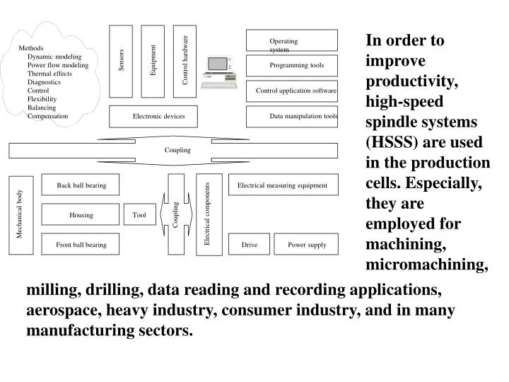
Back ball bearing Electrical measuring equipment Sensors Control hardware Equipment Electrical components Mechanical body Coupling Housing Tool Operating system Methods Dynamic modeling Power flow modeling Thermal effects Diagnostics Control Flexibility Balancing Compensation Front ball bearing Drive Power supply Programming tools Electronic devices Control application software Data manipulation tools Coupling In order to improve productivity, high-speed spindle systems (HSSS) are used in the production cells. Especially, they are employed for machining, micromachining, milling, drilling, data reading and recording applications, aerospace, heavy industry, consumer industry, and in many manufacturing sectors.
Friction Compensation F spindle with friction spindle _ el + F F F spindle _ mi spindle _ ep spindle _ wl Force generator Ideal case Amp + - F spindle _ sf F F d/dt spindle _ ao 1 spindle _ ao + + ò ò m F Correction of non-linear process statics spindle _ cv Viscous friction feedback + +/ - d + Coloumb friction feedback +/ - F *sign( ) Spring Feedback c A translational motion model of a high-speed spindle system
Graphical representation of flow of power within the spindle
EMB ROTOR Figure-16.4 shows the schematic diagram of this custom-built spindle system with respect to optimized design specifications (Refer Table-16.4.)
Speed in Rev. per minute 1876N 1444N 980 N 0 25 50 75 100 125 150 175 200 225 250 275 Time in Seconds Loss due to friction in a typical high speed spindle system. Developers have studied the operating points i.e., the Quotient Point (Q-point) of the rotary systems since long. The Q-point curves, which are the graphic representation of the dynamic model equations, help the engineer to view the performance of the system instantly. Theoretically, the Q-points are described using state space method. Experimentally, they are plotted from the I/O data.
0 5 10 15 20 25 30 35 40 45 In Watt 0 5 10 15 20 25 30 In RPM Loss due to viscous shear of the air in between the stator and rotor of the high speed spindle systems.
-50 0 50 100 150 200 250 300 350 400 450 500 Relative heat generation 0 4 8 12 16 20 24 28 32 36 40 45 50 55 60 65 Time Heat generation with respect to time
Temperature in degree C Front bearing -5 0 15 20 Rear bearing 0 30 60 90 120 150 180 210 Time in Second Temperature with respect to time
Curve No. Curve fitting formula Heating/Without heating 1 18.1*L^0.26 No heating 4 8 1 9 5 3 7 2 6 2 8.1*L^0.37 No heating 3 8.1*L^0.36 No heating 4 7.6*L^0.52 Heating 5 6.3*L^0.45 Heating 6 1.3*L^0.68 - 7 10.1*L^0.30 No heating 8 3.5*L^0.67 Heating 9 9.1*L^0.37 No heating Relationship between axial load and displacement because of thermal deformation
HSSS are vulnerable to vibration. Balancing is an important area as far as design and developme-nt of not only HSSS are concerned but also of other mechatronic systems. Mass unbalances are the major sources of vibration. A powerful balancing method, called Electro-Magnetic Balancing (EMB) technique has been developed in the micromanufacturing laboratory, K-JIST. The photograph of an EMB for HSSS.
1 = Roundness of the Shaft after compensation (EMB) 2= Roundness of the Shaft before compensation 2 Y-axis displacement in micrometer -5 -4 -3 -2 -1 0 1 2 3 4 5 -5 -4 -3 -2 -1 0 1 2 3 4 5 X-axis displacement in micrometer Vibration compensation by the use of Electromagnetic Balancer (EMB). A new technique for compensation of induced mass unbalances.
Model-based DAP, on the other hand rely on quantitative mathematical relation between the I/O (hence model of the plant) and depends only on the availability of a mathematical model of the plant. This involves two tasks, generation of residuals and design of decision rules based on these residuals.
F-1 = Fault due to thermal deformation A measure of radial pressure in exerted F-1 = Fault due to thermal deformation ; Change of Coulomb Friction Coefficient 1 0.8 0.6 0.4 0.2 0 -0.2 0.6 0.5 0.4 0.3 0.2 0.1 0.0 Faulty F-1 Normal Preload applied deliberately Preload applied deliberately F-1 Time 0 300 600 900 1200 1500 Time 0 300 600 900 F-2 = Bearing jam F-2 = Bearing jam 12 10 8 6 4 2 0 0.05 0.04 0.03 0.02 0.01 0.00 -0.01 Power; (VI) Insufficient cooling Insufficient cooling F-2 F-2 Time Time 0 600 1200 1800 2100 2400 2700 0 600 1200 1800 2100 2400 2700 Some FDI results based on spectral analysis and stricture estimation using model equations. Figure illustrates how the strictures are changed with respect to additive faults. (a) Fault due to shaft wear. (b) & (c) Fault due to thermal deformation (d) & (e) Fault due to spindle jam
1. Scope (i) component classification (ii) characterization 2. Model construction (i) Identification of variables (ii) Determination of Validation Life Span Value Formulation Stage 1. Algorithm generation 2. Design (Hw & Sw) 3. Data acquisition Inventory Stage 1. Decision maker ( Watchdog) Tracking Stage 1. Components-based Machine control requirements 2. Distributed Control File handling Display Data Acquisition GUI, Seven segment Miscellaneous Configuration Disk files SEA development knowledge base and workbench
A SEA variable must have a life span value (LSV). Life Span Value (LSV) is defined as a predictable value i.e., LSVs are the measure of active life of the variables defined for a specific component/device.
Parallel connection Sensors Actuators Plant Central Valves Interfacing Controller Switches Drives Controllers Etc.. A schematic diagram of Centralised Control C C Sensors P O N N E L T T C Actuators R W O A O L R Drives L C K N E E R D T S C Etc. A schematic diagram of DCS In resent years industrial automation and control systems preferred to implement Distributed Control System (DCS) instead of centralized, because of its advantage of great flexibility over the whole operating range.
Management level Installation, Binding, Monitor & Control Process/System level SC to OC, Config., Registration (Compiler, COM, DDE, OLE ) Network level Protocol, System image (firmware) Component level Sensors, Actuators, PLCs, PCs (hardware) Distributed control can be leveled into four layers of automation services. Component level is the physical layer that connects devices, PC, industrial PC, PLC, microprocessor, micro-controller etc. Network interface layer is similar to MAC sub-layer of the link layer protocol. Process layer includes application layer features. Application layer defines the variables, which are responsible to transfer data from one place to other when they are connected logically.
Schematic diagram of the spindle system in the context of control interfacing
Graphical User Interface Client Server Object Oriented Virtual design NT, LNS, VB6, OS for DCS, Simulation tool Fieldbus based DCS network System Image Transceiver Transceiver Transceiver N1 N2 N3 Interfacings Interfacings Interfacings Display Alarm, Switch, Buttons Position sensors (Encoders) Temperature And vibration sensors Code-N2 Code-N1 Code-N3 Drive (actuator) HIGH SPPED SPINDLE MACHINE (co-ordination, synchronization, acknowledgement, timing ) Spindle control realization using DCS scheme