Download
1 / 63
640 likes | 795 Views
Offset Quadruple-Ridge Orthomode Transducer, Mode Splitter/Combiner. X-Band OMT Design Review October 1, 2009. Gordon Coutts. Introduction. Low-Band EVLA Circular Polarizers. Circular to Square Transition. Quadruple-Ridge OMT (separates orthogonal linearly polarized signals).

E N D
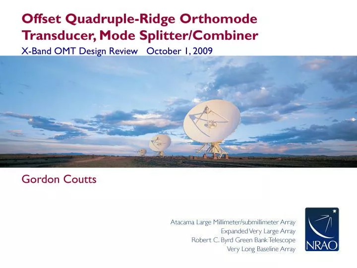
Offset Quadruple-Ridge Orthomode Transducer, Mode Splitter/Combiner X-Band OMT Design Review October 1, 2009 • Gordon Coutts
Low-Band EVLA Circular Polarizers • Circular to Square Transition • Quadruple-Ridge OMT (separates orthogonal linearly polarized signals) • Quadrature Hybrid • Phase-Matched cables connecting the OMT to the hybrid Quadrature Hybrid
High-Band EVLA Circular Polarizers • Circular to Square Transition • Sri’s corrugated waveguide Phase Shifter • 45 Degree offset mode splitter • Bøifot OMT (separates orthogonal linearly polarized signals)
X-Band Design Challenges • Two options using conventional technology from existing EVLA receivers: • Cascaded Bøifot OMT/ mode splitter/ phase shifter • This would scale to an impractically large size at X-band • Direct scaling of the C-Band Polarizer to work at X-Band • This would result in very small dimensions (20 mil chamfer, 30mil ridge gap) • Manufacturing tolerances would be a significant percentage (of the order of 10%) of the scaled dimensions • Narrow ridge dimensions would not readily accommodate set screws/coaxial feeds • Phase matching to an external hybrid would be extremely difficult due to the required cable length adjustments (1.9mil/degree at 12GHz)
Novel X-Band OMT Design • The new X-Band OMT uses a 45 degree offset quadruple-ridge design • The novel polarizer design combines concepts from low-band and high band circular polarizer designs • The OMT combines the function of the ‘45 degree twist’ mode splitter and Bøifot OMT used in the high frequency designs
Novel X-Band OMT Design • Ridges are offset from the square waveguide input by 45 degrees • Square Waveguide Input: 0.947” x 0.947” • Detects circularly polarized signals when used in conjunction with Sri’s waveguide phase shifter • No external quadrature hybrid or phased matched cables in this design
High-Band EVLA Circular Polarizers • Circular to Square Transition • Sri’s corrugated waveguide Phase Shifter • 45 Degree offset mode splitter • Bøifot OMT (separates orthogonal linearly polarized signals)
Proposed EVLA X-Band Circular Polarizer • Circular to Square Transition • Sri’s corrugated waveguide Phase Shifter • 45 Degree offset quadruple-ridge OMT
Compact Design of X-Band OMT • Compact design: OMT Length is 6.12”
X-Band OMT Dimensions • Chamfer profile similar to C-band OMT for manufacturability • 125 mil Ridge Width • 62 mil Ridge Gap • 40 mil Chamfer flat section • Locator block sets ridge gap and maintains symmetry
X-Band OMT Dimensions • The quadruple-ridge waveguide dimensions: • optimum impedance at low-band edge • Eliminate higher order modes • 0.047” semi-rigid coaxial feeds • 62.5mil spaced shorting pins for impedance matching and TE11 trapped-mode resonance suppression • One 2-56 set screw for each sorting pin, with set screws for adjacent pins on opposing ridges
Circularly Polarized Electromagnetic Waves • LCP (Astronomy Definition) • RCP (Astronomy Definition)
y x z
y x z
y x z
y x z
y x z
y x z
y x z
y x z
y x z
y x z
y x z
y x z
y x z
y x z
y x z
y x z
y x z
y x z
y x y x z LCP signal
y y x x Theory of Operation Apparent motion of electric field vector of circularly polarized electromagnetic waves as viewed from the receiver (astronomy definition). LCP signal RCP signal
Direction of Propagation Direction of Propagation y y x x Theory of Operation: Phase Shifter LCP signal RCP signal
y' y x x' Theory of Operation: OMT Port 2 Port 1 Port 2 Port 1 (mode 1) (mode 2)
Port 2 Port 2 Port 1 Port 1 RCP signal output LCP signal output y' y x x' Theory of Operation: OMT LCP signal RCP signal
HFSS Simulated OMT Performance • HFSS simulated modal transmission S-parameter magnitude from OMT input to the coaxial OMT output ports
HFSS Simulated OMT Performance • HFSS simulated reflection OMT S-parameters
Measured Circular Polarization Performance using Machined Prototype Phase Shifters
Machined Phase Shifters • Prototype X-Band phase shifters were fabricated in-house • Used to evaluate circular polarization performance of the new X-Band OMT • The X-Band OMT was connected to the phase shifter and measured using the PNA