Download
1 / 31
310 likes | 426 Views
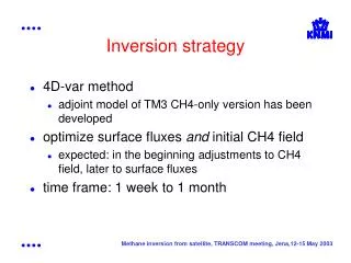
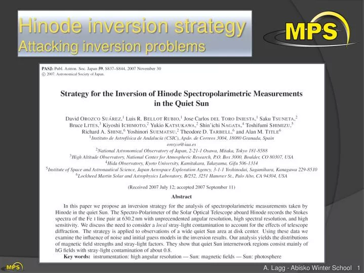
Hinode inversion strategy Attacking inversion problems . Motivation. Why Hinode? spectra are easier to interpret than, e.g. CRISP (continuous WL coverage) straylight effects well studied (and understood) Why Quiet Sun? weak signals: ME appropriate approach

E N D
Motivation Why Hinode? spectra are easier to interpret than, e.g. CRISP (continuous WL coverage) straylight effects well studied (and understood) Why Quiet Sun? weak signals: ME appropriate approach interesting effects, especially concerning straylight
Hinode inversions • diffraction limited observations • angular resolution 0.32´´ (limited by pixel size of 0.16´´) • free from seeing effects • light entering the telescope comes from a much smaller region than for ground based telescopes • results in significantly larger polarization signals • effect of noise is minimized • less atmospheric components mixed together in one resolution element • facilitates the interpretation of data • allows for simpler atmospheric models • Milne-Eddington appropriate CHECK using MHD!
ME approach to complex stratification • Magnetohydrodynamic simulations of the quiet-Sun provides “realistic” model atmospheres: <B>=10, 50, 140 G • Fe I 630.15 and 630.25 nm spectral lines with no noise and not affected by the measurement process • Wavelength sampling 2.15 nm Orozco Suarez et al., 2009 I/Ic Q/Ic U/Ic V/Ic MHD simulations <B>=10G B γ Vögler & Schüssler 2005 φ vLOS Spatial resolution 0.0285″ = 20 km
How to compare MHD and ME? • Atmospheric quantities vary with height • ME inversions provide single quantities that can be interpreted as averages of the real stratifications (Westendorp Plaza et al. 1998) • Analytically, it is possible to determine the “height of formation of a ME measurements” (Sánchez Almeida et al. 1996) • In practice this concept is of little use since the conditions of the atmosphere are not known • The formation height is deeper in intergranular lanes than in granule centers • ME inferences cannot be assigned to a constant optical depth layer • The height at which the ME parameters refer to change depending on the physical parameter
Hinode measurements – spatial degradation • Hinode: 0.5 m telescopewithspatialresolution ~0.26" @ 630 nm (~190km) • Degradation by telescope diffraction ~0.26"
Study using MHD simulations degrade to SOT/SP MHD (SOT/SP res.) substantial loss of contrast (15% 7.5%) 80% of blurred profiles show TCP lower than original This decrease is not due to cancellation of opposite polarity fields, but a true result of the telescope diffraction. It is important to include the stray/scattered light of the surrounding pixels (contamination factor)
Hinode measurements – spatial degradation • Hinode: 0.5 m telescopewithspatialresolution ~0.26" @ 630 nm (~190km) • Degradation by telescope diffraction ~0.26" • Degradation by CCD pixel size ~0.32” • Reduction of rms contrast from 13.7% to 8.5% (the rms contrast of real Hinode/SP observations is ~7.5%) <B>=10G
Telescope diffraction – effect on spectra • Telescope diffraction modifies the shape of the Stokes profiles Black = before ; red = after
Quantitative analysis of ME performance Inferred field strength • Quantitative comparison with the real atmospheric parameters at log τ = -1 • The scatter is a combination of the use of a ME model atmosphere to fit asymmetric Stokes profiles and the pixel-to-pixel variations of the “height of formation” • The deviation of the magnetic field strength from one-to-one correspondence is due to the variation of the height of formation in the magnetic field with the field strength log τ = -1 Inferred field inclination log τ = -1 Blue = mean ; red = rms
ME inferences of solar magnetic fields • Conclusion: ME inversions provide good estimates of the physical quantities present at log τ = -1 • Caution: This differences may be rather large for individual pixels even when the fit is good do not trust individual pixels too much! • The differences associated to the ME approximation dominate against those due to photon noise of the observations • (Orozco Suárez et al., in prep)
How to include straylight? Global straylight: when telescope has wide PSF (pixel contains information also from regions far away) seeing / AO induced wide PSF average quiet Sun profile as straylight component Local straylight: narrow PSF (Hinode) average over I profile of neighboring pixels Should the local straylight be polarized or unpolarized?
Inversion strategy: modeling the stray-light profile Orozco Suarez et al. • Invert the Stokes profiles assuming a homogeneous magnetic atmosphere occupying the whole resolution elements and a contamination of “stray light” • The idea is to correct for the dilution of the polarization signals due to diffraction • The “stray light” profile is evaluated individually for each pixel by averaging the Stokes I profiles within a 1"-wide box centered on the pixel • 10 free parameters are determined (S0, S1, 0, λD, a, B, , , vLOS, ) • This strategy represents a significant improvement over conventional treatments in which a global stray-light profile is considered
Local straylight correction average straylight profile calculated from Stokes I profiles in a 1´´ wide box centered on the pixelHeLIx+: adjustable size of this box add this average profile to the Milne-Eddington profile using a straylight factor α= (1-f), f … filling factor: straylight is interpreted as contamination (degradation of polarization signal due to diffraction). it might also represent magnetic filling factors smaller than one(more on that in the next minutes…) Orozco Suarez et al. (2007) • non-magnetic component (straylight) • magnetic component (ME)
MHD Inversion results (I): qualitative analysis Orozco Suarez (2009) Field strength Inclination Azimuth Real model stratification at log = -2 Results without using stray-light contamination Results using local stray-light contamination
Inversion results (II): qualitative analysis • Mean and rms values of the errors defined as the difference between the inferred and the real parameters at optical depth log τ=-2. Orozco Suarez (2009) Field strength • Field strengths are underestimated if NO stray-light contamination is considered • The inversion considering local stray-light contamination gives • Field strength error < 80 G • Field inclination error < 6º Rms NO stray light Mean Rms WITH stray light Mean
Inversion results (III): stray light factors • dashed: Histogram of stray-light factors derived from the inversion • solid:ratio of TCP in the degraded image with respect to that in the original image Orozco Suarez (2009) • The histogram has a clear peak at 55% • There is a strong resemblance between the two distributions indicating that: the stray-light factors derived from the inversion actually model the effects of telescope diffraction and CCD pixel size • The inferred α’s represent the degradation of the instrument and NOT a real filling factor
Hinode Inversions: internetwork fields Normal map: 10 March, 2007 Exposure time of 4.6s per slit (noise level of 10-3Ic ) Lites et al., 2008
Hinode Inversions: internetwork fields Lites et al., 2008 High S/N map: 27 February, 2007 Exposure time of ~ 60s per slit noise level of 3×10⁻⁴Ic
Hinode Inversions: QS polarization maps Lites et al., 2008
Hinode Inversions: QS polarization maps Lites et al., 2008
Inversion Results: Maps • The supergranular cells are clearly outlined by the network fields • Network fields are characterized by strong field concentrations while the internetwork shows weaker fields • The fields are more vertical in the network and more horizontal in the internetwork • The stray-light factors are of the order of values of ~ 60-80% for the network and 70-90% for the IN
Inversion Results: Maps • The supergranular cells are clearly outlined by the network fields • Network fields are characterized by strong field concentrations while the internetwork shows weaker fields • The fields are more vertical in the network and more horizontal in the internetwork • The stray-light factors are of the order of values of ~ 60-80% for the network and 70-90% for the IN
Results: PDFs for B and INC IN field strength distribution IN field inclination distribution Field strength (G) Field inclination (º) • The IN basically consists of hG flux concentrations • The IN fields tend to be horizontally oriented • The distribution of field strengths has a peak at 90 G and the inclination peaks at 90º • These results are in agreement with the findings of Lites et al. (1996), Keller et al. (1994) • They are in agreement with the results derived from infrared observations (Lin 1995, Lin & Rimmele 1999, Khomenko et al. 2003) and with the simultaneous inversion of visible and infrared lines (MartínezGonzález et al. 2008) • Notice that some fields tend also to be vertical
Results: Granular and intergranular fields IN field strength distribution IN field inclination distribution Field strength (G) Field inclination (º) • 24% of the surface covered by granules in the IN contains magnetic flux detectable above the noise (in intergranules 28%) • Strong fields are less abundant in granules • There is a large fraction of very inclined fields in granules although vertical fields do also exist in granules
Results: Stray light factor contribution Stray-light factor [%] • The distribution of stray-light factors peak at about ~ 80% • The stray-light factor is a combination of: • Reduction of the polarization signals due to diffraction which would produce dilution factors of about 55% • Real filling factor due to insufficient angular resolution • The real magnetic filling factor is f= (1-α) / 0.45 • This corresponds to an average filling factor f ~45%, considerable larger than typical filling factors inferred from ground-based observations at 1”
Results: average fields and flux values • Using the true magnetic filling factors and the high S/N data one can calculate the mean: • magnetic flux density • average field strength • The flux density is of the same order of magnitude of previous estimates at lower spatial resolutions • The flux imbalance is consistent with simulations(Steiner 2008) • The average field strength is close to that obtained from Hanle measurements(Trujillo BuenoShchukina, & Asensio Ramos 2004)
Conclusions: QS Hinode IN fields • The internetwork mostlyconsists in weakfieldconcentrations. • Theaveragemagneticfieldstrengthis 125 Mx/cm2 • Hinodesees the so-called “Hidden QS magnetism” • The reason is that inversionsare able to determine the field strength and its filling factor reliably (Orozco Suárez et al. (2009) to be submitted) • There is still a discrepancy on the flux values and on the interpretation of the field inclinations distribution • We need better spatial resolution to fully resolve the magnetic structures OR to perform image deconvolution • SST/CRISP data, Sunrise IMaX • Exercise: inverting Hinode data with HeLIx+
Continuum normalization: IMAGE requiresSZERO
Continuum normalization: LOCAL NOSZERO
Exercise III:Potential problems with inversions • read Hinode data • parameter crosstalkSGRAD / ETA0 • straylight: local/global • selection of atmospheric model • ambiguities • intrinsic (180° ambiguity) • Flux ↔ B cos(γ) FF • test convergence • small map • convolution (SST data?) • LTE assumption • LS Coupling • ME approximation • … Required:Theoreticians Required:Experience!