Download
1 / 13
130 likes | 233 Views
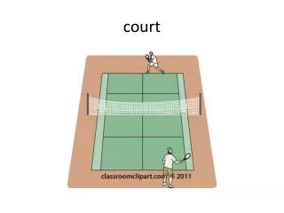
Racquetball Court Sensor. Andy Lai Kevin McCrory ECE 345 – Senior Design. Project Purpose. Eliminate human error in judgement during a racquetball game Provide accurate detection in the lower front corner of the court Ensure the detection system does not obstruct play and court parameters.

E N D
Racquetball Court Sensor Andy Lai Kevin McCrory ECE 345 – Senior Design
Project Purpose • Eliminate human error in judgement during a racquetball game • Provide accurate detection in the lower front corner of the court • Ensure the detection system does not obstruct play and court parameters
Emitters and Detectors • LK11 laser pointer emits a wavelength of 645 nm • Beam reaches up to 1500 ft • MRD 510 photo detector (flat lens) • < 1 ns response time • Amplification
Original Design Wall sensor Output to Device Op Amps D Flip Flops Gain of 10 Slow Clock Floor Sensor Fast Clock
Working Design 555 Timer D Q (( )) J Q D Q High input K Q CLR D Flip Flops Set and Clear are High Op Amps Gain of 10 D R Q PE H CET CEP 10 Hz clock 1 MHz Clock
Truth Tables J = 1 and K = 1 never exists. If exists, output will toggle.
Logic Issues • Holding the buzzer output • Original design did not correct the “wall problem” • Solution: Same as holding the buzzer output • Delay logic simplified with the 555 Timer • 555 Timer eliminates 3 logic components and solves the feedback problem in “wall problem”
Timing and Delay • Approximately 59.6 ns delay from wall sensor to J/K flip flop • Floor must be tripped at a time > 59.6 ns after the wall was tripped 59.6 ns Wall Sensor Floor Sensor Both tripped At J/K F/F
More Timing and Delay • Signal response time • Time = distance / rate • Time = .0127 m / 31.29m/s = .406 ms or 406000 ns • Satisfies detector response time
Testing • Built model racquetball floor • Plexiglass did not impede or diffract the transmission of the laser beam • For simplicity and convenience, two-input toggle switches were used to mimic the sensor during testing • On-going logic tests
Problems and Challenges • Delay logic • Feedback loop in the wall D flip-flop • Continuous D flip-flop failures • Laser pointer battery lifetime
Recommendations • Perform tests with full laser array • Optimize the sensor distance from the floor and the wall • Perform detailed analysis of TTL circuit to ensure functionality of devices • Shrink logic with PLDs or FPGAs for final product • Hardwire lasers to a voltage source to eliminate battery lifetime issue • Implement more sophisticated lasers • Actual field test