Download

1 / 38
380 likes | 389 Views
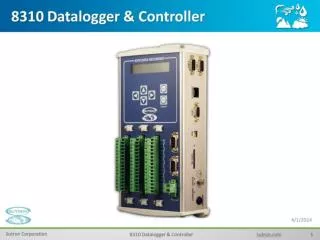
8310 Training. Sutron 8310 Data Logger. Sutron 8310 Data Logger. Power and Sensor Connections. 8310 Design.

E N D
Sutron 8310 Data Logger • Sutron 8310 Data Logger
8310 Design • The overall 8310 design utilizes low-power circuitry to achieve long-life battery operation and provide a rugged system for unattended field operation in extreme environments. For even more durability, each 8310 is tested to operate over the -40C to +60C temp extremes expected in remote environments. Full EMI and transient protection are built into each input.
8310 Capabilities & Features • Simple Front panel setup without PC or other devices. • Terminal interface for setup using PC without custom software. • Built-in measurement circuitry to handle sensors commonly used. • Flexible measurement schedules and logging schemes. • Built-in BASIC to support custom measurements, processing and communications. • Built-in support for GOES, Iridium, GPRS, and telephone modems with both data and speech capabilities. • Dual communications support allowing combinations of supported communications devices. • Remote operation without using custom PC programs. • Weatherproof packaging to promote long product life in the field. • Wide temperature operation to operate reliably in environmental extremes. • Battery operation with low power consumption. • Built-in solar panel regulator.
Telemetry Options • Telephone MODEM with Speech • GOES/METOSAT/INSAT Satellite Transmitter • IRIDIUM Transceiver • GSM/GPRS MODEM
Wide Range of Applications • Flood Warning • Weather Stations • Stage and Precipitation Networks • Dam Safety Monitoring • On-site Recording of many kinds of digital or analog data • Irrigation control
8310 Part Numbers Part Number Description 8310-N 8310, NEMA4 8310-O 8310, NEMA2 8310-N-S 8310, NEMA4, with Satlink* 8310-N-S-G 8310, NEMA4, with Satlink* and GSM/GPRS Modem* 8310-N-S-I 8310, NEMA4, with Satlink* and Iridium SBD transceiver* 8310-N-S-P 8310, NEMA4, with Satlink* and Telephone modem (voice and data) 8310-O-I 8310, NEMA2, with Iridium 8310-O-G 8310, NEMA2, with GSM/GPRS
Ports and Data Download Options • SD Card Socket • USB/COM1 Serial Communications • Ethernet Port • Front Panel 2-Line Display • 6-Buttons: Display/Menu Control
Menus • Complete Front Panel Control - 6 Buttons • PC • Command Line Operation • Menu Driven Interface • Menus are Similar to 8210
PC Command Line Main Menu • Sutron 8310: Main Menu • Station 8310C 09/24/2010 13:56:34 • Recording is ON+TX 9 Meas Active • Alarm Status: NORMAL • M1.O1*: TEMP > 23.971 C G • M2.O1: VBAT > 13.25 G • M3.O1: VBAT_HR > 0.00 U • M4.O1*: AirTemp > 23.53 G • M5.O1: RelHumid > 46.20 G • M6.O1*: Stage > 9.95 G • M7.O1: DewPoint > 18.44 • M8.O1: testdata > 25.46 G • M9.O1: Stage > 0.00 U • Logged Data > • Station Setup > • Terminal Operations > • Diagnostics > • End Main
Terminology • Measurements • Inputs • Processing • Outputs • Alarms • Alerts
Measurements • The 8310 operates to make measurements. Measurements can be as simple as a single value read from a temperature sensor or more complicated like a vector wind speed average or dew point measurement. When a measurement is set up in the 8310, it is given a name and a number. The measurement numbers are M1, M2...
Inputs • Signals from sensors or instruments (like a voltage or resistance) connected to the 8310. • Depending on the type of measurement, the 8310 will need to read one or more inputs • Built-in support for analog, digital, SDI, RS232 and other types of inputs
Processing • Most inputs need some kind of processing to convert the value measured (e.g. a voltage or resistance) into engineering units (like temperature or pressure) • Supports Slope-Offset calculations, Polynomial, Steinhart-Hart, & Lookup Tables to convert the RAW value measured to the desired units
Outputs • Outputs can be displayed, logged, transmitted and used in other calculations and measurements • Some measurement types have just one output while other types have multiple outputs (Avg, Min, Max, Accum, Instant...)
Alarms • Detection of alarms based on comparing a value with a user set hi limit, low limit and/or rate of change limit • Alarm noted in the Alarm status menu
Alerts • Messages Sent Using Communication Devices to Provide Notice of Alarms
Measurement Setup • M1*: TEMP • MeasName TEMP • Enable Yes • MeasType Average • Interval 00:01:00 • Time 00:00:10 • SampleInterval 00:00:10 • SampleDuration 00:01:00 • M1.I1: InputType InternalTemp • TempUnits Celsius • Processing Slope-Offset • Slope 1 • Offset 0 • Cal Slope 1 • Cal Offset 0 • M1.I1: Cur Val 23.9938 Celsius G • M1.O1*: TEMP 23.981 C G • M1.O2*: TEMPMin > 23.98 G • M1.O3*: TEMPMax > 23.98 G • M1.O4*: TEMPCnt > 6.00 G • M1.O5: TEMPSTD > 0.00 G • End M1*: TEMP See Manual Page 68 for details on Meas Types “>”Indicates more info avail, Press Right Arrow to View more Info
Diagnostics /SDI Tools • This menu provides tools useful in operating and maintaining SDI-12 devices. SDI-12 is an industry standard protocol for serial smart sensors. The tools menu provides functions to find devices that have been connected to the SDI-12 bus and communicate with them. • System Status provides a way to view: Recent Logged Messages, SW Version, Communications, Basic, I2C, Serial Number, Num Resets. Diagnostics /System Status
Station SetupThe Station Setup menu provides a way to perform most of the essential functions needed to set up an 8310. A typical Station Setup menu... • Station Setup • Measurements (9) > • Basic > • Communications (4) > • Logs (2) > • Log Records (1) > • Users (0) > • Advanced Settings > • Read setup from file • Write setup to file • Clear setup • Save formatted setup • End Station Setup
Measurements (9) • M1*: TEMP > Sample 5 of 6 • M2: VBAT > Next: 13:57:00 • M3: VBAT_HR > Next: 14:00:00 • M4*: AirTemp > Sample 4 of 6 • M5: RelHumid > Next: 13:57:00 • M6: Stage > Next: 13:57:00 • M7*: DewPoint > Executing • M8: testdata > Next: 13:57:00 • M9: Stage > Next: 14:00:00 • Add Measurement • Delete Measurement • End Measurements See Manual Page 68 for details on Meas Types
Station Setup/Communications • The Station Setup/Communications menu shows all communications ports that are in the system as shown below. From this menu you can see the type of communications configured for each device and the status of each device. You can press RIGHT to see and optionally change the detailed settings for each device. You can change the type of device attached to COM4. You cannot change the com type for COM1, COM2 and COM3 from this menu as these ports are the internal ports and not normally changed by the user. COM1 is always type DIRECT and cannot be changed. You must use the Advanced Settings to change the type of COM2 and COM3. • A typical communications menu is shown below: • Communications (3) • COM1: (Started) DIRECT • COM2: (Started) VOICE • COM3: NO CONNECT • COM4: SATLINK • LAN (Disabled-On) ► • End Communications
Station Setup/Communications • Communications (3) • COM1: (Started) ► DIRECT • COM2: (Started) ► VOICE • COM3: ► NO CONNECT • COM4: ► SATLINK • LAN (Disabled –On)► • End Communications • You can press RIGHT to see and optionally change the detailed settings for each device.
Station Setup/Communications/COMx SATLINK • Satlink COM4 • SatID 00000000 • InitSatlink YES • LocalTimeOffset 0 • SelfTimedSettings > • RandomSettings > • End Satlink
SelfTimed Settings • Enabled Yes • Time 00:00:00 • Interval 04:00:00 • Channel 151 • CenterWindow No • WindowLength 00:00:10 • Type GOES 300 bps • Format SHEF • AppendLatLon No • AppendQuality No • Select outputs > • End SelfTimed Settings
Station Setup/Logs • Logs (2) System.log ► • Data.log ► • Add Log • Delete Log • End Logs
Advanced Settings(LAN Settings) • Use DHCP • Ip Address • Subnet Mask • Default Gateway • Primary DNS • Secondary DNS • Primary WINS • Secondary WINS
Station Setup/Users • Setup User • Full access to see and change measurement setup properties • Retrieval User • Access to view and download log files
Analog Inputs • Number Available 8 • Input Range -0.1 to 5V with respect to ground, single ended or differential • Single Ended Range 0-5 V, + 78 mV (with respect to ground) • Differential Range +2.5V, + 78 mV ( + input with respect to – input) • CMRR 120 dB typ • Input Impedance > 10 Gohm typ • Accuracy: 0.002% of 5V typ 0.003% of 78mV typ HiGain • 0.03% of 19.5mV typ x128Gain • Temp Coefficient 5 ppm/C typ • Ratio Accuracy Limited by A/D resolution • Noise floor RMS noise typically < 1bit on 78mV scale and above • Excitation 2.5V (up to 50 mA) • Protection Multistage input protection including spark gaps. • 4-20 mA Precision load available for 2 analog channels. Loop source voltage provided by switched battery voltage
Digital Inputs • Number Available 4 • Intended for tipping bucket, frequency or discrete inputs (quadrature takes 2 inputs) • Maximum frequency 8kHz, minimum pulse width 100 microseconds • Input range 0-5V (100KOhm pull-up to +5V provided) • Accuracy +0.07% @200 ms sample interval • +0.03% @500 ms sample interval • +0.01% @1000 ms sample interval • Max Quadrature Frequency 4kHz
Switched Voltages Digital Outputs • Number Available 2 • Output type Open collector with 100 ohm current limiting resistor, 100 mA, 15V max • Number Available 2 • Types • Switched battery 12V • Switched +5V
Power Budget • Quiescent (basic model): 4 ma • Quiescent GOES: 10ma • Measuring: 15ma • Transmitting GOES: 3500 ma • Transmitting LOS: 2500 ma • Telephone OFF HOOK: 50ma • Display ON: 83 ma
8310 Design Goals • Replacement for 8210 • Setup Similar to 8210 • No Special GUI SW Needed • Some New Technology • SD Card Slot • USB Serial Port • Ethernet Port