Download
1 / 37
380 likes | 534 Views
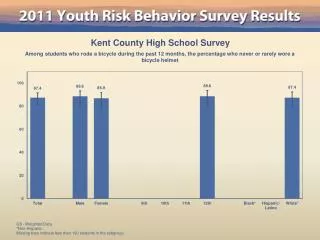
Innovative High Resolution Electrical Resistivity Imaging (ERI) (Aestus’ GeoTrax Survey™) Used to Detect Soil/Groundwater Contamination From Leaking USTs and Other Sources. Presented by Stuart W. McDonald, P.E. President, Aestus, LLC. The 11th National Israeli NDT conference

E N D
Innovative High Resolution Electrical Resistivity Imaging (ERI) (Aestus’ GeoTrax Survey™) Used to Detect Soil/Groundwater Contamination From Leaking USTs and Other Sources Presented by Stuart W. McDonald, P.E. President, Aestus, LLC The 11th National Israeli NDT conference Tuesday, April 27, 2010; Tel Aviv, Israel
Topics Covered Today PROBLEM • Conventional environmental site characterization techniques are and are not producing satisfactory results; Site cleanup too costly • Other historically available technology such as conventional geophysical tools (GPR, EM, Seismic, etc.) not helping enough • Need new approach/tools – look at other industries faced with similar problems (oil/gas; medical) SOLUTION • Environmental consulting and non-traditional geophysics experts from Aestus/Oklahoma State University teamed to develop a subsurface scanning tool that works at virtually any site • This tool has changed paradigms of contamination behavior/distribution in subsurface • Yields lower project costs and faster cleanup
Topics Covered Today (continued) PROOF THAT IT WORKS ● EXAMPLES ● COSTS • Review Case Studies • Validation by EPA’s Ada, Oklahoma laboratory • Validation by State Regulators • Validation by Environmental Consultants • Backed up by University Research and Peer Reviewed Publications QUESTIONS & ANSWER SESSION
Monitoring Well (Typ.) Monitoring Well (Typ.) LNAPL GW Level Soil Core Previously Unknown LNAPL ? ? ? Interpreted Contact Confirmed Contact Typical Site Characterization
Recovery/monitoring Well (Typ.) Defined Contact Location Actual image from a refinery LNAPL recovery system Previously Unknown LNAPL …and thus allows reality-based decisions
WOULD YOU HAVE SURGERY WITHOUT A CAT-SCAN/MRI/X-RAY? Why do this with your environmentally impacted sites?
Medical X-ray MRI Sonogram Petroleum Seismic Gravity Magnetics Environmental Drill Probe Excavate • Environmental • Drill • Probe • Excavate • Medical • X-ray • MRI • Sonogram • Petroleum • Seismic • Gravity • Magnetics And you thought medical surgery is expensive! Sampling array at the Cape Cod Site; over 10,000 subsurface sampling ports. –USGS-
What is Electrical Resistivity Imaging (ERI)? • Based on • DC resistivity techniques (>100 yrs old) • Computing/electronics power (<10 yrs old) • Instead of 10’s of data, collect thousands (high data density) • Analogous to “Geological Digital Photography” • Provides map of electrical properties of the subsurface
Aestus Proprietary Supplemental Field Equipment Proprietary OSU/Aestus Data Acquisition Algorithms Proprietary OSU/Aestus Data Reduction/ Processing Standard Electrical Resistivity Techniques High Resolution Subsurface Image That is “Drillable”
How ERI Works – “Setting Up The Camera” • 56 Electrode Stakes (3/8-inch diameter) Hammered Into Ground • Geophysical Cables Attached to Electrode Stakes • Data Collection Starts (~1-2 Hours; Site Dependent) “Take Only Pictures…Leave Only Footprints”!
How ERI Works – “Taking the Picture” Four Electrodes Yield One Measurement Data Point (“pixel”) One Data Point or “Pixel”
How ERI Works – “Focusing the Camera” (1.5 m Survey) 271 feet long 54 feet deep (2.0 m Survey) 361 feet long 72 feet deep (2.5 m Survey) 451 feet long 92 feet deep (* Optimal Choice) (3.0 m Survey) 541 feet long 108 feet deep Target Imaging Depth
Iterative Measurements Yield Matrix of Data Points or “Pixels” Proprietary Software Generates Subsurface 2-D Image from Data Set Suspected LNAPL “Blob” Below LUST Depth (feet) A “Kilo-pixel” Digital Camera Taking Electrical Picture of Subsurface How ERI Works – “Developing the Film”
How ERI Works – Viewing Multiple “Pictures” Together 3-D Perspective View - GeoTrax SurveysTM (From Above and Looking North at All On-Site Surveys) LEGEND: Current UST Tank Basin Former UST Basins Existing Remediation Wells NAPL “Blobs” Below LUST’s ERI Output – 2-D Data “Fences” in 3-D Space
How ERI Works – Viewing the Data in 3-D & 4-D Pre-Remediation 36 ohm-m ~ 20,000 mg/kg TPH 2-D Data Fences 7 mos. into Remediation 46 ohm-m ~ Free Product (LNAPL) Pre-Remediation 46 ohm-m ~ Free Product (LNAPL)
NAPL “Blobs” Shown in 3-D 3-D ERI Model Output from GeoTrax SurveyTM Data How ERI Works – Viewing the Data using 3-D Model
Technological Progression • Data acquisition now 100x faster than 1990 • Data processing now 350x faster than 1990 • Images were not “drillable” – OSU/Aestus created dramatically improved images – Images can “see” resistive subsurface targets others can’t
Standard ERI methods barely able to detect “blob” with the highest concentration of LNAPL detected on this site • Second LNAPL “blob” does not show up using standard ERI LNAPL 21,283 mg/kg TPH 45 mg/kg TPH • OSU’s/Aestus’ ERI Methods detect both LNAPL “blobs” present • Image shows concentrations in a semi-quantitative manner • Images are “Drillable” LNAPL 21,283 mg/kg TPH 45 mg/kg TPH * Confirmation Drilling Data Collected by EPA; Images from Golden, OK Site Case Study
after Halihan et al, 2005 “Simple” LNAPL plume: • Undergone pump-and-treat and a surfactant flush • At least 92 wells on the site • Is the site “clean” now?
SB-1 SB-1 268 50 ft wide x 25 ft depth SB-2 SB-2 Total Petroleum Hydrocarbons (TPH in mg/kg) vs. Depth
SB-3 22 SB-3 SB-4 2.5 SB-4 Total Petroleum Hydrocarbons (TPH in mg/kg) vs. Depth
Separate “Blobs” SB-5 SB-6 Total Petroleum Hydrocarbons (TPH in mg/kg) vs. Depth SB-5 SB-6 0.4 45
0 Depth (ft) 30 0 Distance (ft) 180 (meters) (meters) Data Density Comparison – NAPL Site Sampling data indicate that these monitoring wells are clean…. 0 Depth (ft) LNAPL 21,283 mg/Kg LNAPL 45 mg/Kg 30 0 180 Distance (ft) Aestus’ GeoTrax Survey™ shows that monitoring well data was not representative of site conditions Actual Research Site - Anomaly soil sampling data provided by EPA Ada, OK Laboratory
0 Depth (ft) 30 To approach the data density of an Aestus GeoTrax Survey™, approximately 35 monitoring wells/soil borings would be required every ~5 feet along a 185 ft transect 0 180 Distance (ft) At ~US$3,500 per monitoring well, cost would be ~US$122,500 and takes weeks At ~US$2,500 per GeoTrax Survey™, cost would be US$2,500 and take only 2-3 hours * Above budgetary costs do not include mobilization/demobilization; survey costs vary depending on site constraints
This is a “magic bullet” SB-2 This is not Complex sites are still complex, you just have a better tool to obtain sufficient data.
Every site is different- there are infinitesimal combinations of lithology, pore fluids, pore structure, contamination, and previous remediation attempts. We don’t have a “magic” resistivity scale that categorizes every site. Images MUST be calibrated in order to provide the best interpretation.
Other Potential Applications in Israel • Sinkhole Detection • Clandestine Tunnel Detection
For Finding Tunnels/VoidsIn Subsurface Computer Modeling Predicts: • Success Using GeoTrax Survey™ • Failure Using Standard ERI
(Not enough resolution to detect small tunnels; confirmed by Israel MOD testing) (GeoTrax Survey™) (Data indicates probable success; untested to date)
TunnelTrax Survey™(Conceptual Approach)Scale-Up to Provide Continuous Subsurface Scanningat Country Border
Located Caves in Anhydrite Gypsum Located Coal Mines Below Former Gas Station • Suspected LNAPL • “Blobs” • Suspected • Locations of Flooded Coal Mines
Sink hole detection Homeland Security – Terrorist Tunnels; Illegal Immigration Tunnels Brownfields Site Characterization for Property/Liability Transfer Point of Compliance Site Boundary Monitoring (Dedicated System) Groundwater/Surface Water Interaction Optimize Locations for Water Wells Salt Water Intrusion into Drinking Water Wells Geotechnical Engineering Landfill Leakage Others
Thank You AdditionalQuestions? Stop Drilling Blind!
Dr. Todd Halihan Oklahoma State University School of Geology 105 Noble Research Center Stillwater, OK 74078 todd.halihan@okstate.edu Stuart W. McDonald, P.E. Aestus, LLC 2605 Dotsero Court Loveland, CO 80538 1.888.Geo.Trax or (970) 278-4090 swm@aestusllc.com www.aestusllc.com