Download
1 / 32
470 likes | 876 Views
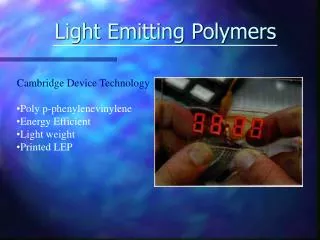
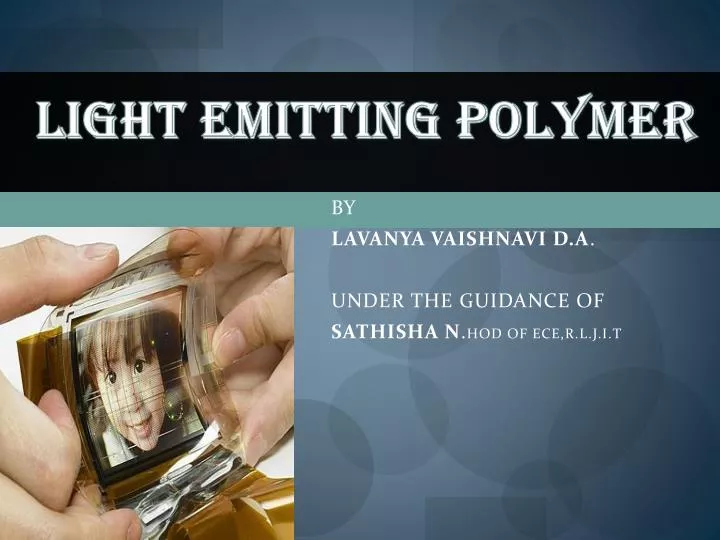
LIGHT EMITTING POLYMER. BY LAVANYA VAISHNAVI D.A . UNDER THE GUIDANCE OF SATHISHA N . HOD OF ECE,R.L.J.I.T. Need this report mail me iam_ vaishnavi@yahoo.com. AGENDA. Introduction LEP Construction and working Ink jet printer Active Matrix and passive Matrix

E N D
LIGHT EMITTING POLYMER BY LAVANYA VAISHNAVI D.A. UNDER THE GUIDANCE OF SATHISHA N.HOD OF ECE,R.L.J.I.T
Need this report mail me • iam_ vaishnavi@yahoo.com Light emitting polymer
AGENDA • Introduction • LEP • Construction and working • Ink jet printer • Active Matrix and passive Matrix • Basic principle and technology • Light emission • Advantages and Disadvantages • Applications • Future application • Conclusion • Bibliography. Light emitting polymer
Introduction • After watching the breakfast news on TV, you roll up the set like a large handkerchief, and stuff it into your briefcase. • Somewhere in the Kargil sector, a platoon commander of the Indian Army readies for the regular satellite updates that will give him the latest terrain pictures of the border in his sector. • All these are possible usingLEP Light emitting polymer
LIGHT EMITTING POLYMER • Schematic of a 2-layer LEP: • 1. Cathode (−), 2. Emissive Layer, 3. Emission of radiation, 4. Conductive Layer, 5. Anode (+) Light emitting polymer
A voltage is applied across the LEP such that the anode is positive with respect to the cathode. This causes a current of electrons to flow through the device from cathode to anode. • Electrostatic forces bring the electrons and the holes towards each other and they recombine liberating light. • In organic semiconductors holes are more mobile than electrons. The recombination causes a drop in the energy levels of electrons, accompanied by an emission of radiation. Light emitting polymer
CONSTRUCTION • Anode-Indium Tin Oxide • Cathode- Aluminum • Polymer- poly phenylene vinylene Light emitting polymer
Light-emitting devices consist of emitting layers sandwiched between a cathode and an anode. • Single-layer devices typically work only under a forward DC bias. • In order to manufacture the polymer, a SPIN-COATING MACHINE is used. • The robot pours the plastic over the rotating plate, which, evenly spreads the polymer on the plate. This results in an extremely fine layer of the thickness of 100 nanometers. • Once the polymer is evenly spread, it is baked in an oven to evaporate any remnant liquid Light emitting polymer
INK JET PRINTING Light emitting polymer
Use of inkjet printing for PLED displays • This technique is now at the forefront of developments in digital electronic materials deposition. • Red, green and blue polymer solutions are jetted into well defined areas with an angle of flight deviation of less than 5º. • The film thickness uniformity may have to be better than ±2 per cent.. Light emitting polymer
Active matrix • Active Matrix LEP displays are much more complex. • Because they have a cathode layer that is an integrated back plane they are able to produce very high resolution images and handle large amounts of data at one time. • This display quality is made possible by polysilicone thin-film-transistors which have very high current carrying capability and switching speed. • Because of these TFTs, active matrix displays have the ability to control each individual pixel independently. Light emitting polymer
Passive matrix • Passive Matrix LEP displays are the simplest form of LEP. • These displays are useful in providing limited information for devices such as cell phones, wristwatches, and other simple display applications. The construction of these OLEDs is based on a set “rib” pattern of the cathode materials and organic layers. • Drivers at the end of each row or column control where the voltage is supplied, and subsequently which ribs produce the image. Light emitting polymer
BASIC PRINCIPLE AND TECHNOLOGY Light emitting polymer
The properties of the spherical s orbital and bimodal p orbitals combine into four equal , unsymmetrical , tetrahedral oriented hybridized sp3 orbitals. This is known as a ‘sigma’ bond • A conjugated ‘pi’ bond refers to a carbon chain or ring whose bonds alternate between single and double (or triple) bonds. The bonding system tends to form stronger bonds than might be first indicated by a structure with single bonds • Unlike the ‘sigma’ bond electrons, which are trapped between the carbons, the ‘pi’ bond electrons have relative mobility. Light emitting polymer
LIGHT EMISSION Electroluminescence : • The energy is released when an electron from the conduction band falls into a hole in the valence band. • The electronic device that accomplishes this electron-hole interaction is that of a diode, which consists of an n-type material (electron rich) interfaced with p-type material (hole rich). • The mobility of electrons and holes are limited to the linear or branched directions of the molecule. The efficiency of electron/hole transport between polymer molecules is also unique to polymers. Light emitting polymer
Electron and hole mobility occurs as a ‘hopping’ mechanism which is significant to the practical development of organic emitting devices. • PPV has a fully conjugated backbone as a consequence the HIGHEST OCCUPIED MOLECULAR ORBIT (HOMO)of the macromolecule stretches across the entire chain, this kind of situation is ideal for the transport of charge; in simple terms, electrons can simply "hop" from one π orbital to the next since they are all linked. Light emitting polymer
Figure demonstration of the full conjugation of π • The delocalized π electron clouds are colored yellow. • PPV is a semiconductor. Semiconductors are so called because they have conductivity that is midway between that of a conductor and an insulator. • Semi-conductors require modest amounts of energy in order to carry a current, and are used in technologies such as transistors, microchips and LEDs. Light emitting polymer
Band theory is used to explain the semi-conductance of PPV. • In a diatomic molecule, a molecular orbital (MO) diagram can be drawn showing a single HOMO and LUMO, corresponding to a low energy π orbital and a high energy π* orbital. • Every time an atom is added to the molecule a further MO is added to the MO diagram. Thus for a PPV chain which consists of ~1300 atoms involved in conjugation, the LUMOs and HOMOs will be so numerous as to be effectively continuous, this results in two bands, a valence band (HOMOs, π orbitals) and a conduction band (LUMOs, π* orbitals). PPV has a band gap of 2.2eV .Figure shows a series of orbital diagrams. • HOMO- highest occupied molecular orbit • LUMO-Lowest unoccupied molecular orbit Light emitting polymer
• A diatomic molecule has a bonding and an anti-bonding orbital, two atomic orbitals gives two molecular orbitals.. • • A single atom has one atomic obital • • A triatomic molecule has three molecular orbitals, as before one bonding, one anti-bonding, and in addition one non-bonding orbital. • • Many atoms results in so many closely spaced orbitals that they are effectively continuous. The orbital sets are called bands. In this case the bands are separated by a band gap. Light emitting polymer
ADVANTAGES AND DISADVANTAGES • ADVANTAGES • Require only 3.3 volts and have lifetime of more than 30,000 hours. • • Low power consumption. • • Self luminous. • • No viewing angle dependence • OLED TVs are really thin - the Sony XEL-1 for example is just 3mm thick. The new prototypes by Sony are merely 0.3mm thick! • OLEDs have a much better viewing angle - almost 180 degrees. Light emitting polymer
DISADVANTAGES • Because they are made out of organic compounds, some have a tendency to “die out” before others.“ Reds and blues die first, leaving a very green display”. • Red and green typically last between 10,000 and 40,000 hours, while blue compounds begin to die at around 1,000 hours. Additionally, the brightness to which your display is set has a tremendous effect on longevity. Light emitting polymer
Engineering and Production • As in any new technology cost is usually a barrier to mainstream production. • Water is also a problem in which engineers need to solve before LEPs can be mass marketed. Because the organic compounds are water soluble it is necessary to create a sealant that will keep out all moisture but still keep the capabilities that make LEPs so advantageous. • When these two hurdles can be overcome OLEDs will become a very viable display alternative to LCD, Plasma, and projection devices. Light emitting polymer
APPLICATIONS • PHOTOVOLTAICS PLED technology can be used in reverse, to convert light into electricity. Devices which convert light into electricity are called photovoltaic (PV) devices, and are at the heart of solar cells and light detectors. Light emitting polymer
POLY LED TV • LEPs TVs are really thin - the Sony XEL-1 for example is just 3mm thick. The new prototypes by Sony are merely 0.3mm thick! Light emitting polymer
TRANSPARENT OLEDS • While there seem to be zero to few readily available uses of transparent OLEDs (TOLEDs) in the consumer market today, the technology exists for wide spread use in the future. Light emitting polymer
FUTURE DEVELOPMENTS Light emitting polymer
NEWS AND INFORMATION • Imagine a day when you are reading a newspaper that is capable of showing pictures and video, is continuously updating itself with the latest news via Wi-Fi connection, and is also so thin and flexible that you can roll it up and put it in your backpack or briefcase. • “That day may someday be a reality thanks to OLED technology” Light emitting polymer
ADVANCEMENTS IN THE HOME • One of the many possibilities is to replace regular walls or windows with similar sized OLED installations which will “lead to user-definable window spaces". • These walls will use transparent OLEDs that will make it possible to have certain areas opaque while other areas clear, depending on what the homeowner would like. Additionally, “the wall can be any color or design that you want. Light emitting polymer
OLED PASSPORT • Samsung SDI from Germany have designed the OLED passport which is claimed to be completely manipulation-proof. • The OLED display will be able to display both video and text containing information about the passport holder. Light emitting polymer
Conclusion • Organic electronics are already entering commercial world. Multicolor automobile stereo displays are now available from Pioneer Corp., of Tokyo. • Royal Philips Electronics, Amsterdam is gearing up to produce PLED backlights to be used in LCDs and organic ICs. • The first products using organic displays are already in the market. And while it is always difficult to predict when and what future products will be introduced • The portable and light weight organic displays will soon cover our walls replacing the bulky and power hungry cathode ray tubes. Light emitting polymer
Bibliography. • www. cdtltd.co.uk • www. research.philips.com • www. covion.com • www.ieee.com • D.Rwdinger, R.Farshchi and V.Subramanian. “Inkjet passive component and plastic substrate”. 2003 IEEE Device Research conference digest pp.187-188, 2003 • Josephine B.Lee and Vivek Subramanian. “Ink Jet Passive devices” 2003 IEEE Device Research conference digest, 2003 Light emitting polymer