Download
1 / 36
380 likes | 618 Views
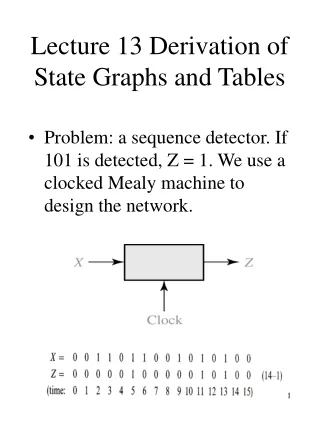
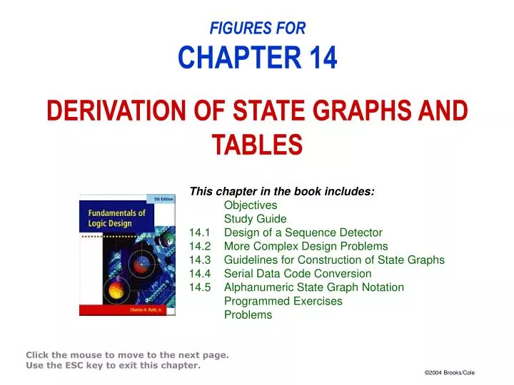
This chapter in the book includes: Objectives Study Guide 14.1 Design of a Sequence Detector 14.2 More Complex Design Problems 14.3 Guidelines for Construction of State Graphs 14.4 Serial Data Code Conversion 14.5 Alphanumeric State Graph Notation Programmed Exercises Problems.

E N D
This chapter in the book includes: Objectives Study Guide 14.1 Design of a Sequence Detector 14.2 More Complex Design Problems 14.3 Guidelines for Construction of State Graphs 14.4 Serial Data Code Conversion 14.5 Alphanumeric State Graph Notation Programmed Exercises Problems FIGURES FORCHAPTER 14DERIVATION OF STATE GRAPHS AND TABLES Click the mouse to move to the next page. Use the ESC key to exit this chapter.
Figure 14-20a:Mealy Circuit for NRZ-to-Manchester Conversion
Figure 14-20b:Mealy Circuit for NRZ-to-Manchester Conversion
Figure 14-20cd:Mealy Circuit for NRZ-to-Manchester Conversion
Figure 14-21a:Moore Circuit for NRZ-to-Manchester Conversion
Figure 14-21b:Moore Circuit for NRZ-to-Manchester Conversion (c) State table