Download
1 / 24
260 likes | 641 Views
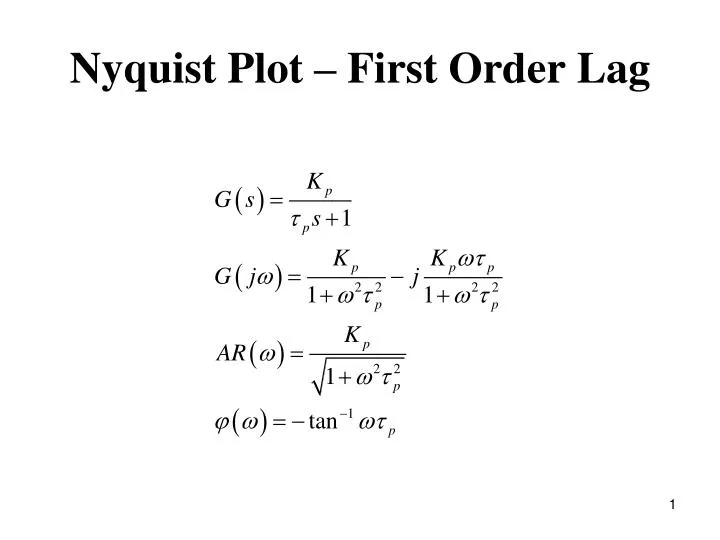
Nyquist Plot – First Order Lag. Nyquist Plot – First Order Lead. Nyquist Plot – Time Delay. Nyquist Plot – FOPDT. Nyquist Plot – Integrator. Nyquist Plot – Integrator and 1 st Order Lag. Nyquist Plot – 2 nd Order Underdamped System. Nyquist Diagrams. Consider the transfer function. with.

E N D
Nyquist Diagrams Consider the transfer function with and
Figure 13.12 The Nyquist diagram for G(s) = 1/(2s + 1) plotting and
Figure 13.13 The Nyquist diagram for the transfer function in Example 13.5:
Frequency Response Characteristics of Feedback Controllers Proportional Controller. Consider a proportional controller with positive gain In this case , which is independent of w. Therefore, and
Proportional-Integral Controller. A proportional-integral (PI) controller has the transfer function (cf. Eq. 8-9), Substitute s=jw: Thus, the amplitude ratio and phase angle are:
Ideal Proportional-Derivative Controller. For the ideal proportional-derivative (PD) controller (cf. Eq. 8-11) The frequency response characteristics are similar to those of a LHP zero: Proportional-Derivative Controller with Filter. The PD controller is most often realized by the transfer function
Figure 13.10 Bode plots of an ideal PD controller and a PD controller with derivative filter. Idea: With Derivative Filter:
PID Controller Forms • Parallel PID Controller. The simplest form in Ch. 8 is Series PID Controller. The simplest version of the series PID controller is Series PID Controller with a Derivative Filter.
Figure 13.11 Bode plots of ideal parallel PID controller and series PID controller with derivative filter (α = 1). Idea parallel: Series with Derivative Filter: