Download
1 / 18
180 likes | 305 Views
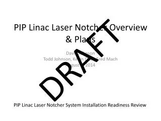
Laser Notcher Status. Dave Johnson, Todd J ohnson, John Sobolewski, Kevin Duel, Andrea Saewert September 11,2013. Tasks/Components. Optical Pulse Generator Fiber pre-amplifier Fiber final amplifier Free space amplifier Pulse shaping and transport Optical Cavity

E N D
Laser Notcher Status Dave Johnson, Todd Johnson, John Sobolewski, Kevin Duel, Andrea Saewert September 11,2013
Tasks/Components • Optical Pulse Generator • Fiber pre-amplifier • Fiber final amplifier • Free space amplifier • Pulse shaping and transport • Optical Cavity • Timing and Controls • Installation
Optical Pulse Generator • Consists of • CW seed laser • 10 GHz LiNb03 modulator with RF Amp & Bias feedback control • RF arbitrary waveform generator (AWG) • PO has been issued for a 2 GS/s AWG with an external fractional clock module which will generate the 201.25 MHz few ns pulses at Booster injection revolution frequency (450.75 kHz) • Initial estimate for the pulse generator was ~$20K final cost ~$6.5K • The AWG & clock module to be housed in a PCI slot expansion box • The complete system has been bread boarded and tested. • The OPG will be packaged for installation (all major components have been ordered and received). Andrea Saewert will help with the layout and packaging. We would like to complete this task by the middle of next month (or sooner, if possible)
Laser Notcher Pulse requirements 15 Hz Linac cycle rep rate ~22 us 67 ms ~50-60 ns Notch pulse: There are approx 9-10 notch pulses/linac cycle ~2.2 us ~22 us ~0.5 -1.5 ns 200 MHz laser pulse structure. There are approx. 9- 12 200 MHz laser pulses each 450 kHz notch pulse ~ 5 ns
OPG test results Purple- RF Amp out AWG: Chase Scientific DA12000 & CG6000 module Yellow- AWG Green – signal form 1.2 GHz PD measuring laser pulses out of fiber pre-amplifier One set of 201.25 MHz pulses 450.75 kHz burst of 201 MHz pulses Pre-distortion of EOM pulses Individual 201.25 MHz temporally uniform pulses
Fiber pre-Amplifier • We have verified the operation of the 100 mW and 2 Watt fiber pre-amplifiers from PriTel meet specifications. • Neither were spec’d for “auto shutdown” to turn off pump when laser seed goes away or drops below s threshold • If the fiber is pumped with out a seed present it can “auto q-switch” and potentially damage itself or other components. • This occurred in the 2W amp when the preamp power was at a low amplification. Consequently, the pump diode on the 100 mW pre-amp was damaged and several fiber connectors in the chain were damaged. This was repaired by PriTel under warranty. • The two amplifiers are to be returned to PriTel to combine them in a single unit adding the “auto shutdown” feature, computer control, and fusion splicing the two amplifiers together. This will be re-packaged into a compact 19” rack mount module. Could be done this year. Est. on the order of $5K.
Final Fiber Amplifier • The final fiber amplifier increases the laser pulse energy from 370 nJ to ~ 10 uJ (x26) and will bring the laser out into free space for injection into the final stage amplifier (free space DPSS amplifier –> gain of ~200) • Peak power is ~5kW and if the amplifier is run CW the average power is 50W. We have specified an option to pulse the amplifier at 15 Hz which reduces the average power to 16 mW. • We wanted an “off the shelf” unit, but it is not available for our specifications. • We have two options for bringing the laser into free space • Install the laser head on the optics table with the free-space amplifier, beam shaping optics, and transport optics. • Purchase a fiber delivery system so that the laser head may be removed from the optics table and the laser delivered to the table via an armored fiber with a collimation port. This will allow the bulk of the module to be installed with the OPG and fiber pre-amp at a remote location. • We have received four bids for the fiber and will be evaluating these over the next couple of days to award a PO by the end of the week. We should stay under the Req. value of $50K
Free Space DPSS Amplifier • Working with Northrop Grumman Cutting Edge Optical on design of free space amplifier • They have supplied amplifier module for NML (for photocathode laser amplifier) and LBL (for pulsed laser stripping tests) • Modules are OEM (robust) • Initial simulations showed with input pulse energy of 10 nJ (initial estimate) requires 3 amplifier modules (2 RBA and 1 RBE). With increase in final fiber amplifier gain it looks like we can supply ~ 10 uJ pulses which will reduce complexity to 2 and maybe even 1 module. • Required gain in DPSS for 10 uJ pulses to produce 2 mJ pulse is x200 (i.e. 23 dB) • DPSS system costs need revision - initial estimate (from NGCEO) on the order of $100K for three modules not including optics/isolators between modules) reducing the number to 2 or 1 module will bring costs down by 10-20%. • Once we get final fiber amplifier and understand its real output proceed with detailed design (and costing) for DPSS. Realistically, time frame would be first next year • The estimate (from NG) for the three modules, controllers, diode pump power supplies, and chiller was ~$100K • Increasing the initial seed energy, thus reducing the complexity may save one or both RBA modules thus reducing the price by ~$18-36K
Pulse Shaping and Transport • Pulse shaping optics which transforms a transform limited Gaussian beam into a spatially uniform rectangular beam with dimensions of 1mm (H) by 6-8mm (V) includes • Cylindrical lens telescope to image the beam on a diffractive optical device to create a top hat profile • PiShaper module form AdlOptica used to create a collimated top hat profile. • Anamorphic prism pair to reduce the size of the horizontal dimension • This collimated top hat laser beam is transported to the input of the vacuum chamber/zig-zag cavity fine position/angle control are performed with a pair of piezoelectric mirrorson the optics table. • Purchase piezoelectric mirror holders and controller ~$2K • All transport will be in enclosed in beam tube. • We have demonstrated the formation of a rectangular top-hat distribution with these components using a green alignment laser. • The optics of the PiShaper are pretty sensitive and more work is required to optimize the beam shaping/transport system.
Optical Cavity • Optical cavity design highly constrained due to limited space. < 2” from RFQ flange sealing surface. • Number of bounces (21) reduces required laser power by factor of 21. • Laser path matches velocity of H- which determines mirror separation (3.37 cm) and reflection angle (2.288o) • John Sobolewski (M.S. co-op) made 3D design and model with input from Todd Johnson and Dave Johnson • 3D model tested with 532 nm laser (it worked very nicely) • Test highlighted changes to better optimize design • Kevin Duel/Todd Johnson to work with Fred Mach (ADMS contract drafter) to finalize changes and produce fabrication prints -> would like to have drawings by mid-October • University of Born ( Igor Kreslo & Michele Weber) interested in collaboration -> potential fabrication of vacuum chamber and optical cavity • Mirror alignment done on bench – no alignment after installation • Need to order optical view ports (AR coated for 1064nm) ~$1800 • Need to order final cavity mirrors (>99.95% reflectivity) ~ $3800 • Need design for optical BPM’s and diagnostic camera/beam dump for tuning the laser through the optical cavity.
Optical cavity 3D printed prototype Attach to RFQ Laser IN Laser OUT Interface with MEBT Mirrors at 2.288o wrt H- beam showing 21 interactions
Optical cavity tests Test set-up Fixed mirror Moveable mirror
Timing and Controls • Need to time the laser pulses to start notching 2.218 us after the section of the linac pulse removed by the 400 MeV chopper. • The 201.25 MHz pulse structure needs to be synchronized to the linac bunch structure • Preliminary meeting with Mike Kucera, Peter Prieto, Andrea Saewert to discuss timing and synchronization. • Work with Bill Pellico to get timing signals • The timing card developed for the LPM looks like it can be used for control. • Need to start looking seriously at available signals and develop specifications • Dave Slimmer to develop LabView Control system Notches created by laser Ntrev 2 us removed by 400 MeV Chopper
Installation • Very crowded space • Optical table needs to be close to RFQ. • Horizontal or vertical mounting • Currently beam shaping, transport optics and DPSS module with isolators (and potentially AOM) installed on optical table (approx size 2’x3’, maybe smaller). • Investigate removing DPSS amplifier and using fiber delivery potentially a HC-PCF) to the Beam Shaping Optics. This will minimize the size of optical table close to the RFQ. This is a “long shot” • LD pump supplies need to be close to DPSS modules. • OPG/fiber amplifiers need to installed together • AWG/timing module/computer can be located farther away such as racks of old 750 chopper • Initial walk through showed just how crowded the space is. Need to get inventive.
Rack Space Real Estate AWG Potential AOM ~7” 4 slot VME crate w/ timing card LD driver/controller (RBA) LD driver/controller (REA) Controls Optical Pulse Generator ~9” OPT OUT RF IN 2W Pre-Amplifier(s) RBA 1.2 kW PS OPT IN Free Space Amplifier (for 2 modules) OPT OUT REA 3 kW PS ~15” 50W Fiber Amplifier OPT IN Trigger IN Optical fiber delivery to optics table This assumes the DPSS is mounted on the optics table along with the beam shaping & transport optics. Fiber Amplifier