Download
1 / 17
170 likes | 304 Views
CESRTA Measurement of Electron Cloud Density by TE Wave and RFA. Ben Carlson Grove City College Mentors: Mark Palmer, John Sikora, and Mike Billing Cornell University Laboratory for Elementary-Particle Physics. Electron Cloud Effect. The Electron Cloud

E N D
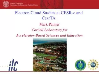
CESRTA Measurement of Electron Cloud Density by TE Wave and RFA Ben Carlson Grove City College Mentors: Mark Palmer, John Sikora, and Mike Billing Cornell University Laboratory for Elementary-Particle Physics
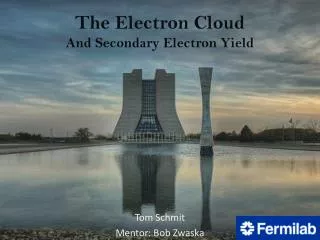
Electron Cloud Effect • The Electron Cloud • Synchrotron radiation ejects low energy photoelectrons from beam pipe • Low energy electrons can be accelerated by positron bunches, causing ejection of secondary electrons Schematic of EC build-up in a vacuum chamber, due to photoemissionand secondary emission [Courtesy F. Ruggiero] REU Talk
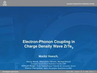
Motivation • ILC will require beams with very small volume in phase space • Accomplished by sending the beam through a damping ring • Synchrotron photons remove the transverse component of momentum • Electron cloud effects are a known difficulty in regimes the proposed parameters of the ILC • Electron cloud tends to induce coupled oscillations and destabilize the beam Cornell LEPP Template
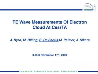
Techniques for Measuring EC • Retarding Field Analyzers • Measures electron flux in a localized region • Application of a potential can be used to measure energy spectrum • Transverse Electric Wave (TE Wave) • Phase shift of carrier proportional to density of electron “plasma” • Measures electron density over an extended region Cornell LEPP Template
TE Wave Setup in the L3 Region BPM48W BPM49 BPM48E Chicane Q48W Q49 Q48E Solenoid Spectrum Analyzer
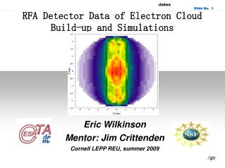
TE Wave Carrier With Sidebands 2GeV plot of dB vs frequency REU Talk
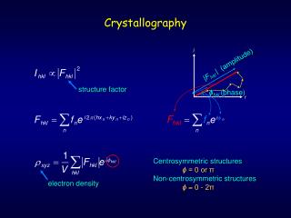
Comparison with RFA data Courtesy: Joe Calvey
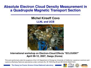
Wigglers 5GeV 4ns spacing REU Talk
Conclusions & Goals • There is much to be explained regarding TE Wave measurements, though likely the TE Wave technique will not resolve the local effects and or artifacts seen in RFA data • Try to determine spatial extent of TE Wave through modeling and measurements • Compare extent with RFA method • Determine whether resonance structure can be observed by TE Wave • Evaluate cloud mitigation techniques for application in the ILC
Beampipe EM wave Low-energy electrons Phase velocitychangesin the ec region frev/Ntrain Positron current E-Cloud Density Relative phase shift TE Wave Measurements Induced phase modulation in the propagation of EM waves through the beampipe Positron bunch train plasma frequency 2c(πere)1/2 Cesr ring Gap EM Wave Gaps in the fill pattern set the fundamental modulation frequency (1st sideband). Higher order components depend on the transient ecloud time evolution during the gap passage. [Courtesy S. De Santis]
Wigglers 5GeV 4ns spacing REU Talk
Wigglers 5GeV 4ns spacing REU Talk
Splitter/Combiner Schematic Used for Both Drive and Receiver Lengths of legs are chosen to give 180 phase shift at 1.7GHz