Download
1 / 21
240 likes | 480 Views
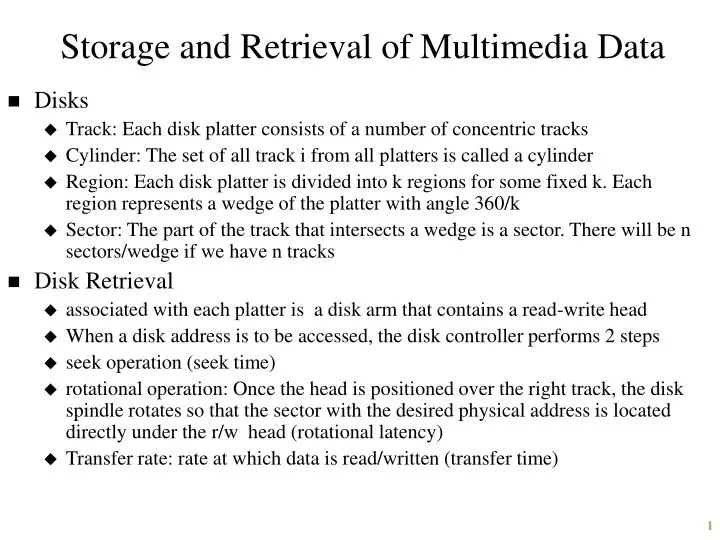
Storage and Retrieval of Multimedia Data. Disks Track: Each disk platter consists of a number of concentric tracks Cylinder: The set of all track i from all platters is called a cylinder

E N D
Storage and Retrieval of Multimedia Data • Disks • Track: Each disk platter consists of a number of concentric tracks • Cylinder: The set of all track i from all platters is called a cylinder • Region: Each disk platter is divided into k regions for some fixed k. Each region represents a wedge of the platter with angle 360/k • Sector: The part of the track that intersects a wedge is a sector. There will be n sectors/wedge if we have n tracks • Disk Retrieval • associated with each platter is a disk arm that contains a read-write head • When a disk address is to be accessed, the disk controller performs 2 steps • seek operation (seek time) • rotational operation: Once the head is positioned over the right track, the disk spindle rotates so that the sector with the desired physical address is located directly under the r/w head (rotational latency) • Transfer rate: rate at which data is read/written (transfer time)
RAID-0 Architecture • RAID (redundant array of inexpensive disks) • Object is divided into blocks (e.g., Object B (b0 …b4) • We have a set of n disks, labeled 0,1, (n-1) • A k-stripe is a set of k drives for some integer k < n which divides n • When storing a set b0, b1, br-1 of contiguous blocks in terms of k striped layout, we store each block b0 on disk 0, b1 on disk 1, b2 on disk 2, ..
RAID-0 Architecture • Object B is stored in a 3-striped layout whereas object C in 4-striped Controller b1 c0 b4 c4 b0 b3 c3 b2 c1 c5 c2 c6 disk 0 disk 1 disk 2 disk 3 • The controller can directly read blocks b0,b1 and b2 in parallel • The transfer rate is almost 3-fold • Major disadvantage is reliability: if a disk crashes, then the system as a whole crashes
RAID-1 Architecture • Uses double the number of disks and the other half is used as mirror disks to eliminate RAID-0 problem • Works on the assumption that there is a low probability that a disk and its mirror crash at the same time • read is done from any one copy • when write occurs, it must be written to two copies • The obvious disadvantage: only 50% utilization of storage (the price paid for reliability)
RAID-5 Architecture • RAID 2-4 also exist • RAID-5 is probably the best: it has a simple but elegant strategy to trade-off between efficient storage utilization and reliability • Each cluster of k disks has a parity disk • If k = n, we have only one cluster • The data in the parity disk is derived from all n disks (for those who are interested: exclusive-OR of all disks) • In the event of a disk crash, it is possible to reconstruct the content of the disk from the parity disk • Disadvantage: If the parity disk crashes, or if two or more disks crash at the same time, RAID-5 is not effective
Service Algorithms • Given a set of clients each of whom wants to read data from the disk, how do we schedule their reads? • These algorithms must execute very fast (i.e. it cannot take too long to determine order of reads) • Some well known algorithms • First Come First Serve (FCFS) • SCAN • SCAN Earliest Deadline First (SCAN-EDF)
First Come First Serve • Each client request has an associated timestamp • Clients are serviced in order of their timestamp • Suppose the disk read head is currently over track i, sector j • FCFS will serve requests in the order r2,r1,r4,r3 • The last 2 columns are completely ignored by FCFS ReqID ReqTime Est.Seek Est.Rot.Delay r1 10 24 3 r2 8 12 5 r3 14 30 6 r4 11 18 4
SCAN • Suppose the disk read head is currently over track i, sector j • We order requests in the order of the number of tracks to be traversed from track i, moving either outwards first and inwards, or vice versa, but not both • We then service the requests in the order prescribed • Assume each track requires 3 units of time to be traversed • If we assume that all of r1-r4 are in tracks beyond track i (i.e., between track i and the outer rim of the disk) then the service order is r2,r4,r1,r3 ReqID ReqTime Est.Seek Est.Rot.Delay r1 10 24(8) 3 r2 8 12(4) 5 r3 14 30(10) 6 r4 11 18(6) 4
SCAN-EDF • EDF stands for “earliest deadline first” • Group all requests in ascending order of their deadline • Each group then is services using SCAN • Assume we have 2 groups G1 (r1,r4) and G2 (r2,r3) • G1 is serviced first using SCAN, i.e, in the order r4,r1 • Next G2 with order r2, r4 • Thus the overall service order is r4,r1,r2,r3 ReqID ReqTime Est.Seek Est.Rot.Delay Deadline r1 10 24(8) 3 100 r2 8 12(4) 5 120 r3 14 30(10) 6 120 r4 11 18(6) 4 100
Building disk-based media servers • Must service multiple clients simultaneously • Clients may want, in addition to playback, other interactive operations like rewind, fast forward, pause, etc. • For each client, the server must • provide continuous playback • this requires filling clients buffer at just the “right” rate • If too fast, buffer might get overwritten • If too slow, client might experience service interruption
Commercial Systems • Dell and many computer manufacturers • Storage Dimensions (the popular) • recently merged with Artecon (www.artecon.com) • provides a range of disk arrays based on RAID architecture • its SuperFlex 5500 system has a capacity of 255GB with peak transfer rates of 80MB/sec • 2 SuperFlex 5500 can be configured/SCSI channel, and 8 such systems can be supported on an single Intel-based server with four SCSI buses to provide capacities around 2TB • hot-swappable • Seagate’s Cheetah System • 36.5GB with transfer rate 80MB/sec • Ciprico • offers several series of RAID arrays • 20, 40, 100MB/sec transfer rates • http://www.europe.access.com/
Retrieving of Multimedia Data from CD-ROMs • CD-ROM driver typically contains one platter • It contains a single spiral track, that is traversed by the read head • Spiral track is divided into equal sized sectors • Unlike a disk drive system where the disk head moves at a constant angular velocity, in a CD-ROM system, the disk head moves at a constant linear velocity across these tracks • Storage: few GBs • Cheaper ($1/disk) • Writable disks are available • Commercial Systems (http://www.baber.com) • Toshiba, NEC Multispin, IBM
Reading from a CD-ROM • Reading is done in rounds • Each round starts with the read head at location 1 • At any given round, we attempt to read a sorted (in ascending order of sector number) set of sectors • Example • Assume a particular CD-ROM contains 100 sectors • The read head is currently at location 58 • A client wishes to read sectors 10,30,50,70,90 • The client has enough buffer to accommodate only 3 sectors • Possibility 1: read sector 70 first, then 90, 10, 30, 50 • Most CD-ROM drivers do not allow this possibility • Possibility 2: Reset the disk head to point 0, and then move the head so that sectors 10,30,50 get buffered. We then consume 10 and buffer 70. Next we consume 30 and buffer 90, next consume 50,70,90
Buffer Requirements • Need to ensure 2 properties • Continuity of playback: the client should be able to read data from the buffer without any interruption • Buffer utilization: at no time should the buffer get over-written • Minimal buffer size is a function of • bandwidth of the disk to prefetch buffer • buffer filling time • decompression rate • compression ratio • consumption rate of the client
Scheduling Retrieval from CD-ROMs • FCFS • Processes requests according to the arrival time • Total seek time is abs(si - si-1)/lv, where lv is the linear velocity, S0 is 1 • Consider serving requests for sectors 25,5,35,15,5,10 and assume lv is 2 sectors/msec • Total seek time = (abs(25-1) + abs(5-25)+ abs(35-5)…)/2 = 54.5msec
Scheduling Retrieval from CD-ROMs • SCAN • Collect a set of requests and sort the sectors in the increasing order of seek distance • If the read head is not initially in the start location, then this might lead to a bidirectional sweep • Requests: 25,5,35,15,5,10 • Sorted order: 5,10,15,25,35 • 5 is read only once, unlike FCFS • Assume the read head is at position 1 • Seek time = ((5-1) + (10-5) + …)/lv = 17 msec • SCAN-EDF • request order: 15 20 10 35 50 • deadline: 10 5 10 10 5 • Service order: 20,50,10,15,35
Retrieval of Multimedia Data from Tapes • 3 basic tape recording mechanisms • serpentine recording • helical recording • transverse recording • Often there is a Robotic tape library and a fixed set of players • the robotic arm reaches into the library, retrieves a requested tape, and inserts it into an available player
Serpentine tapes • Tape contains several tracks that are parallel to the length of the tape • Each track has a track number and a linear set of tape blocks • When reading, • the tape is first rolled forward (in the left to right direction) and the read-head of the driver is positioned over track 1 • when we reach the end of track 1, the read-head gets repositioned over track 2, and we read contents of track 2 moving from right to left • in track 3 we read from left to right • The process continues till we reach the end of the tape
Reading from serpentine tapes • Suppose the read head is currently positioned over track 4 and we are reading block 90 on this track • Suppose we wish to read block 10 on track 1. • Alternative 1: • The tape must be rewound to the beginning of track 4, then the read head must be switched to track 1 (jumping tracks 2, 3) and finally move the head to block 10 • Many systems do not support such jumps • Alternative 2: • Fast forward tape to the right till the read head is positioned over the last lock of track 4 • Reposition the read head to track 1 • Rewind the tape until the read head is positioned over block 10
Helical tape recording • Tracks are diagonal • tape winds around a cylinder in a spiral fashion • read/write heads are embedded on the surface of the cylinder • the axis across which the cylinder rotates is somewhat tilted, relative to the tape • the head pass the linear movement of the tape, different parts of the tape, corresponding to angular, diagonal tracks • When writing a block, • the written block is immediately read • if the read value is different from what is to be written (use checksum), mark this block as a bad sector, rewrite it in the next block,
Robotic tape libraries • Relative cost of obtaining the tape from the shelf and loading it in the drive is a very expensive operation • Thus minimizing such accesses is a key requirement • Striping technique (as in RAID) is used • granule size and Stripe width: Both impact retrieval efficiency • e.g, media object of size 200MB, granule size 20MB, stripe width 3 • Commercial systems • Storage Dimensions • SuperFlex tape array system has 168GB capacity • MegaFlex 192GB with 20MB/sec transfer rate • Transitional Technology:20-40GB with transfer rates of 3-6MB/sec • IBM’s MAGSTAR system: 40GB