Download
1 / 93
940 likes | 1.06k Views
Coronagraph for diagnosing beam halo T. Mitsuhashi KEK. Everything was start with astronomer’s dream……. Eclipse is rare ph enomena, and only few second is available for observation of sun corona, prominence etc . Artificial eclipse was dream of astronomers, but……. The eclipse

E N D
Coronagraph for diagnosing beam halo T. Mitsuhashi KEK
Everything was start with astronomer’s dream…… Eclipse is rare phenomena, and only few second is available for observation of sun corona, prominenceetc. Artificial eclipse was dream of astronomers, but……..
The eclipse Inside umbra : total eclipse Penumbra : Partial eclipse 3.84 x 10⁵ km 1.49 x 10⁸ km
Why we can see sun corona by eclipse without diffraction fringe? The area of umbra>>>diameter of objective lens Because no aperture between sun and moon. It means no strong diffraction source in eclipse. Question is can we make same system with artificial way?
Compare two setup, eclipse and artificial eclipse. Answer is to eliminate diffraction fringe from aperture. …but how???? Diffraction source aperture is in here.
Compare two setup, eclipse and artificial eclipse. Diffraction <<corona Diffraction >>corona Answer is to eliminate diffraction fringe from aperture. …but how???? Diffraction source aperture is in here.
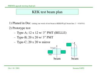
Magnifier lens Objective lens Opaque disk to block glare of central image 1. Diffraction fringes vs. halo Observation with normal telescope
Convolution between diffraction fringes and object profile Diffraction fringes Gaussian profile
Diffraction makes fringes surrounding from the central beam image.Intensity of diffraction fringes are in the range of 10-2 -10-3 of the peak intensity.The diffraction fringes disturb observation of week object corona surrounding which has intensity range of 10-5 -10-6 of bright sun sphere.
Convolution between diffraction fringes and beam profile Diffraction fringes Gaussian profile Blocked by opaque disk
By following reasons, we cannot observe beam halo by using same condition of eclipse Due to small beam size, the umbra size is small, and we cannot put an objective lens with enough diameter. Distances between beam and opaque disk are too short, we cannot focus onto both of them in the same focal plane.
Can we make same system for the observation of beam halo? The area of umbra,<diameter of objective lens Distances between beam, opaque disk and objective lens are short and beam is too small!
The coronagraph to observe sun corona Developed by B.F.Lyot in 1934 for a observation of sun corona by artificial eclipse.Special telescope having a “re-diffraction system” to eliminate the diffraction fringe.Following explanation for the coronagraph is based on in section 26 special optical system in “Wave optics” written by H.Kubota (unfortunately, this good textbook is written in Japanese).
Anti-reflection disk Field lens Relay lens Baffle plate (Lyot stop) Objective lens Opaque disk Baffle plates to reduce reflection Optical system of Lyot’s corona graph
1st stage : Objective lens system 2ed stage : re-diffraction system 3ed stage : Relay lens 3 stages-optical system in the Lyot’scoronagraph
Objective lens
Objective lens with anti-reflection disk to block reflected light from opaque disk
Disturbance of light F(x) on opaque disk is given by; In here f(h) is disturbance of light on objective lens.
R r Objective lens diffraction The integrationperformsrandR r: radius of Anti-reflection disk R: radius of objective lens aperture
Using Babinet’s theorem (same technique in the appodization) , F(x) on opaque disk is given by
Opaque disk Function of the field lens : make a image of objective lens aperture onto its focal plane Field lens Objective lens Re-diffraction optics system Re-diffraction optical system Opaque disk
x1 x2 Field lens diffraction The integrationperformsx1andx1 x1: radius of field lens x2: radius of opaque disk
Disturbance of light on Lyot’s stop by re-diffraction system is given by;
Intensity distribution of diffraction fringes on focus plane of field lens Geometrical image of the aperture of objective lens
Field lens Objective lens Re-diffraction optics system Re-diffraction optical system Opaque disk Opaque disk Function of the field lens : make a image of objective lens aperture onto Lyot stop
Opaque disk Field lens Lyot stop Objective lens Re-diffraction optics system Re-diffraction optical system Opaque disk Function of the field lens : make a image of objective lens aperture onto Lyot stop Blocking diffraction fringe by
x1 Relay lens diffraction The integrationperformsh1 h1: radius of Lyot stop
Disturbance of light on final focus point V(x) is given by; U(x) is still not 0 inside of relay lens pupil!
Relay of corona image to final focus point Blocking diffraction fringe by Lyot stop
This leakage of the diffraction fringe can make background level 10-8 to -9 (depends on Lyot stop condition). Diffraction fringe exists here Re-diffraction intensity on the Lyot stop Background in classical coronagraph
Photographs of coronagraph Front view of the coronagraph
Objective lens with anti-reflection disk to block reflected light from opaque disk
View from the back side Field lens Lyot’s stop
Zoom up of opaque disk. Shape is cone and top-angle is 90º
Background source in coronagraph • Noisefrom defects on the lens surface (inside) such as scratches and digs. • 2. Noise from the optical components (mirrors) in front of the coronagraph. • 3. Reflections in inside wall of the coronagraph. • 4. Noise from dust in air. • 5. Rayleigh scattering from air molecule.
Background source in coronagraph • Noisefrom defects on the lens surface (inside) such as scratches and digs. • 2. Noise from the optical components (mirrors) in front of the coronagraph. • 3. Reflections in inside wall of the coronagraph. Apply baffles • 4. Noise from dust in air. Apply dust filter • 5. Rayleigh scattering from air molecule. • Not significant in few ten meter optical path
5mm S&D 60/40 surface of the lens
Noise source in the pupil has two effects, • Refraction in noise source • phenomena in sun or moon halo is produced by this effect. • Mie scattering by noise source • opaque dust or dig on lens or on any optical components are classified this effect. • Dust in air also has same effect.
Sun halo Moon halo Sun light is refracted by hexagonal ice crystal and making 22deg halo
Effect 2: Digs on glass surface serves as diffraction source in the pupil
A Big problem is the nose sources produce another halo!!
A Big problem is the nose sources produce another halo!! It is not easy to distinguish from intrinsic beam halo.