Download

1 / 151
1.52k likes | 1.69k Views
Lower Power Design Guide. 1998. 6.7 성균관대학교 조 준 동 교수 http://vlsicad.skku.ac.kr. Contents. 1. Intoduction Trends for High-Level Lower Power Design 2. Power Management Clock/Cache/Memory Management 3. Architecture Level Design Architecture Trade offs, Transformation

E N D
Lower Power Design Guide 1998. 6.7 성균관대학교 조 준 동 교수 http://vlsicad.skku.ac.kr
Contents • 1. Intoduction • Trends for High-Level Lower Power Design • 2. Power Management • Clock/Cache/Memory Management • 3. Architecture Level Design • Architecture Trade offs, Transformation • 4. RTL Level Design • Retiming, Loop-Unrolling, Clock Selection, Scheduling, Resource Sharing, Register Allocation • 5. partitioning • 6. Logic Level Design • 7. Circuit Level Design • 8. Quarter Sub Micron Layout Design • Lower Power Clock Designs • 9. CAD tools • 10. References
Portable Mobile (=ubiquitous =nomadic) Systems with limited for heat sinks Lowering power with fixed performance: DSPs in modems and cellular phones Reliability: Increasing power ! increasing electromigration, 40-year reliability guarantee (product life cycle of telecommunication industries) Adding fans to reduce power cause reliability to plummet. Higher power leads to higher packaging costs: 2-watt package can be four times greater than a 1-watt package Myriad Constraints: timing, power, testability, area, packaging, time-to-market. Ad-Hoc Design: Lack a systematic process leading to universal applicability. Motivation
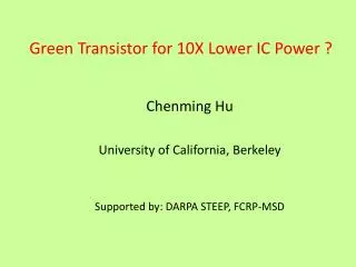
Power Dissipation in VLSI’s I/O I/O clock clock memory clock I/O clock logic MPU1 MPU1 ASSP1 memory ASSP2 memory memory logic I/O logic MPU1: low-end microprocessor for embedded use MPU2: high-end CPU with large amount of cache ASSP1: MPEG2 decoder ASSP2: ATM switch
Energy-hungry Function by Network Server: Infopad (univ. of California, Berkeley), weight < 1 pound, 0.5W (reflective color display) + 0.5W (computation,communication, I/O support) = 1W (Alpha chip: 25W StrongARM: 215 MHz at 2.0V:0.3W) runtime 50 hours, target: 100MIPS/mW. Deep-sub micron (0.35 - 0.18) with low voltage for portable full motion video terminal; 0:5m : 40 AA NiMH; 1m : 1 AA NiMH System-On-A-Chip to reduce external Interconnection Capacitances Power Management: shut down idle units Power Optimization Techniques in Software, Architecture,Logic/Circuit, Layout Phases to reduce operations, frequency, capacitance, switching activity with maintaining the same throughput. Current Design Issues in Lower Power Problem
Static: Leakage current(<< 1%) Dynamic: Short Circuit power(10-30%): Short circuit ow during transitions, Switching (or capacitive) power(70-90%): Charging/discharging of capacitive loads during transitions Power Component
Vdd vs Delay • use architecture optimization to compensate for slower operation, e.g., Parallel Processing and Pipelining for concurrent increasing and critical path reducing. • Scale down device sizes to compensate for delay (Interconnects do not scale proportionately and can become dominant)
Synthesis and Optimization Pareto point
LCD: 54.1%, HDD 16.8%, CPU 10.7%, VGA/VRAM 9.6%, SysLogic 4.5%, DRAM 1.1%, Others: 3.2% 5-55 Mode: Display mode: CPU is in sleep-mode (55 minutes), LCD (VRAM + LCDC) CPU mode: Display is idle ( 5 minutes), Looking up - data retrival Handwrite recognition - biggest power (memory, system bus active) Power Consumption in Multimedia Systems
DPM (Dynamic Power Management): stops the clock switching of a specific unit generated by clock generators. The clock regenerators produce two clocks, C1 and C2 . The logic: 0.3%, 10-20% of power savings. SPM (Static Power Management): saving of the power dissipation in the steady mode. When the system (or subsystem) remains idle for a significant period time, then the entire chip (or subsystem) is shut-down. Identify power hungry modules and look for opportunities to reduce power If f is increased, one has to increase the transistor size or Vdd. Power Management
Power Management(christian.piguet@csemne.ch) • use right supply and right frequency to each part of the system If one has to wait on the occurence of some input, only a small circuit could wait and wake-up the main circuit when the input occurs. • Another technique is to reduce the basic frequency for tasks that can be executed slowly. • PowerPC 603 is a 2-issue (2 instructions read at a time) with 5 parallel • execution units. 4 modes: • Full on mode for full speed • Doze mode in which the execution units are not running • Nap mode which also stops the bus clocking and the Sleep mode which stops the clock generator • Sleep mode which stops the clock generator with or without the PLL (20-100mW). • Superpipelined MIPS R4200 : 5-stage pipleline, MIPS R4400: 8 stage, 2 execution units, f/2 in reduce mode.
TI • Two DSPs: TMS320C541, TMS320C542 reduce power and chip count and system cost for wireless communication applications • C54X DSPs, 2.7V, 5V, Low-Power Enhanced Architecture DSP (LEAD) family: Three different power down modes, these devices are well-suited for wireless communications products such as digital cellular phones, personal digital assistants, and wireless modem,low power on voice coding and decoding • The TMS320LC548 features: • 15-ns (66 MIPS) or 20-ns (50 MIPS) instruction cycle times • 3.0- and 3.3-V operation • 32K 16-bit words of RAM and 2K 16-bit words of boot ROM on-chip • Integrated Viterbi accelerator that reduces Viterbi butterfly update in four instruction cycles for GSM channel decoding • Powerful single-cycle instructions (dual operand, parallel instructions, conditional instructions) • Low-power standby modes
Power Estimation Techniques • Circuit Simulation (SPICE): a set of input vectors, accurate, memory and time constraints • Monte Carlo: randomly generated input patterns, normal distributed power per time interval T using a simulator switch level simulation (IRSIM): defined as no. of rising and falling transitions over total number of inputs • Powermill (transistor level): steady-state transitions, hazards and glitches, transient short circuit current and leakage current; measures current density and voltage drop in the power net and identifies reliability problem caused by EM failures, ground bounce and excessive voltage drops. • DesignPower (Synopsys): simulation-based analysis is within 8-15% of SPICE in terms of percentage difference (Probability-based analysis is within 15-20% of SPICE).
Cache/Memory Management • Clock and memory consumes between 15% to 45% of the total power in digital computers • As block size increases, the energy required to service miss increases due to increased memory access external-memory access (530 mA) vs. on-chip access(300mA): Replacing excessive accesses to background memory by foreground memory • Cache vertical partitioning (buffering): multi-level variable-size caches Caches are powerdown when idle. • Cache horizontal partitioning (subarray access): several segments can be powered individually. Only the cache sub-bank where the requested data is located consumes power in each cache access. • Using distributed memory instead of a single centralized memory • Locality of reference to eliminate expensive data transfer across high capacitance busses • Cache misses consume more energy (directed-mapping or k-associated mapping?), page faults consume more energy
Block Power Management (Sleep, standby mode) Scheme by Enabling Clock Clock Power Management Scheme by adding Clock Generation block Power Management
Architectural-level Synthesis • Translate HDL models into sequencing graphs. • Behavioral-level optimization: • Optimize abstract models independently from the implementation parameters. • Architectural synthesis and optimization: • Create macroscopic structure: • data-path and control-unit. • Consider area and delay information • Hardware compilation: • Compile HDL model into sequencing graph. • Optimize sequencing graph. • Generate gate-level interconnection for a cell library. of the implementation.
Spatial locality: an algorithm can be partitioned into natural clusters based on connectivity Temporal locality: average lifetimes of variables (less temporal storage, probability of future accesses referenced in the recent past). Precompute physical capacitance of Interconnect and switching activity (number of bus accesses) Architecture-Driven Voltage Scaling: Choose more parallel architecture Supply Voltage Scaling : Lowering V dd reduces energy, but increase delays System-Level Solutions
Software Power Issues Upto 40% of the on-chip power is dissipated on the buses ! • System Software : OS, BIOS, Compilers • Software can affect energy consumption at various levels Inter-Instruction Effects • Energy cost of instruction varies depending on previous instruction • For example, XORBX 1; ADDAX DX; • Iest = (319:2+313:6)=2 = 316:4mA Iobs =323:2mA • The difference defined as circuit state overhead • Need to specify overhead as a function of pairs of instructions • Due to pipeline stalls, cache misses • Instruction reordering to improve cache hit ratio
Avoiding Wastful Computation • Preservation of data correlation • Distributed computing / locality of reference • Application-specific processing • Demand-driven operation • Bus-Inverted Coding • Transformation for memory size reduction • Consider arrays A and C are already available in memory • When A is consumed another array B is generated; when C is consumed a scalar value D is produced. • Memory Size can be reduced by executing the j loop before the i loop so that C is consumed before B is generated and the same memory space can be used for both arrays.
Architecture Lower Power Design • Optimum Supply Voltage Architecture through Hardware Duplication (Trading Area for Lower Power) and/or Pipelining • complex and fewer instruction requires less encoding, but larger decode logic! • Use small complex instruction with smaller instruction length (e.g., Hitachi SH: 16-bit fixed-length, arithmetic instruction uses only two operands, NEC V800: variable-length instruction decoding overhead ) • Superscalar: CPI < 1: parallel instruction execution. VLIW architecture.
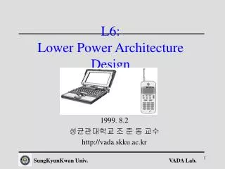
Computational work varies with time. An approach to reduce the energy consumption of such systems beyond shut down involves the dynamic adjustment of supply voltage based on computational workload. The basic idea is to lower power supply when the a fixed supply for some fraction of time. The supply voltage and clock rate are increased during high workload period. Variable Supply Voltage Block Diagram
Power Reduction using Variable Supply • Circuits with a fixed supply voltage work at a fixed speed and idle if the data sample requires less than the • maximum amount of computation. Power is reduced in a linear fashion since the energy per operation is fixed. • If the work load for a given sample period is less than peak, then the delay of the processing element can be increased by a factor of 1/workload without loss in throughput, allowing the processor to operate at a lower supply voltage. Thus, energy per operation varies.
Data Driven Signal Processing The basic idea of averaging two samples are buffered and their work loads are averaged. The averaged workload is then used as the effective workload to drive the power supply. Using a pingpong buffering scheme, data samples In +2, In +3 are being buffered while In, In +1 are being processed.
Power and Area 1.5V and 10MHz clock rate: instruction and data memory accesses account for 47% of the total power consumption.
Memory Parallelization At first order P= C * f/2 * Vdd2
Architecture Trade-Off Ppipeline = (1.15C)( 0.58V)2 (f) = 0.39P NON-PIPLELINED Implementation Pparallel = (2.15C)(0.58V)2 (0.5f) = 0.36P PIPLELINED Implementation
Application Specific Coprocessor • DSP's are increasingly called upon to perform tasks for which they are not ideally suited, for example, Viterbi decoding. • They may also take considerably more energy than a custom solution. • Use the DSP for portions of algorithms for which it is well suited, and craft an application-specic coprocessor (i.e., custom hardware) for other tasks. • This is an example of the difference between power and energy • The application-specific coprocessor may actually consume a more power than the DSP, but it may be able to accomplish the same task in far less time, resulting in a net energy savings. • Power consumption varies dramatically with the instruction being executed.
VLIW Architecture Compiler takes the responsibility for finding the operations that can be issued in parallel and creating a single very long instruction containing these operations. VLIW instruction decoding is easier than superscalar instruction due to the fixed format and to no instruction dependency. The fixed format could present more limitations to the combination of operations. Intel P6: CISC instructions are combined on chip to provide a set of micro-operations (i.e., long instruction word) that can be executed in parallel. As power becomes a major issue in the design of fast -Pro, the simple is the better architecture. VLIW architecture, as they are simpler than N-issue machines, could be considered as promising architectures to achieve simultaneously high-speed and low-power.
Synchronous VS. Asynchronous SYSTEMS • Synchronous system: A signal path starts from a clocked flip- flop through combinational gates and ends at another clocked flip- flop. The clock signals do not participate in computation but are required for synchronizing purposes. With advancement in technology, the systems tend to get bigger and bigger, and as a result the delay on the clock wires can no longer be ignored. The problem of clock skew is thus becoming a bottleneck for many system designers. Many gates switch unnecessarily just because they are connected to the clock, and not because they have to process new inputs. The biggest gate is the clock driver itself which must switch. • Asynchronous system (self-timed): an input signal (request) starts the computation on a module and an output signal (acknowledge) signifies the completion of the computation and the availability of the requested data. Asynchronous systems are potentially response to transitions on any of their inputs at anytime, since they have no clock with which to sample their inputs.
Asynchronous SYSTEMS • More difficult to implement, requiring explicit synchronization between communication blocks without clocks • If the signal feeds directly to conventional gate-level circuitry, invalid logic levels could propagate throughout the system. • Glitches, which are filtered out by the clock in synchronous designs, may cause an asynchronous design to malfunction. • Asynchronous designs are not widely used, designers can't find the supporting design tools and methodologies they need. • DCC Error Corrector of Compact cassette player saves power of 80% as compared to the synchronous counterpart. • Offers more architectural options/freedom encourages distributed, localized control offers more freedom to adapt the supply voltage
6% more logics Example: ABCS protocol


![[DOWNLOAD]⚡️PDF✔️ Extreme Fitness: How to Train Like An Action Hero](https://cdn7.slideserve.com/12929157/takeoff-a-visual-guide-to-training-and-monitoring-dt.jpg)