Download
1 / 29
290 likes | 405 Views
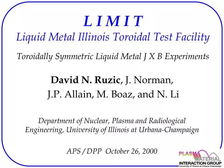
L I M I T Liquid Metal Illinois Toroidal Test Facility Toroidally Symmetric Liquid Metal J X B Experiments. David N. Ruzic , J. Norman, J.P. Allain, M. Boaz, and N. Li Department of Nuclear, Plasma and Radiological Engineering, University of Illinois at Urbana-Champaign

E N D
L I M I TLiquid Metal Illinois Toroidal Test FacilityToroidally Symmetric Liquid Metal J X B Experiments David N. Ruzic, J. Norman, J.P. Allain, M. Boaz, and N. Li Department of Nuclear, Plasma and Radiological Engineering, University of Illinois at Urbana-Champaign APS / DPP October 26, 2000
Outline • Motivation • Experiment • Pool Experiments • Flow Experiments • Analysis • Future Work • Acknowledgments
Motivation • Flowing liquid metal walls can… • withstand high heat fluxes • rapidly remove heat • withstand disruptions • reduce impurity influx • introduce new operating regimes • Will they work as we expect? • Build a device and test the LIMITs
LIMIT -- LIquid Metal Illinois Toroidal test facility SS support structure 40 cm height Ga reservoir Pyrex center column Pyrex reservoir 40 Coils
LIMIT --- Top view 50 cm diameter
LIMIT Characteristics • 40 coils of 12 Gage wire. R=0.13 Ohms • 27 V creates 200 Amps and produces 1000 Gauss at outside radius of center column • 5 kW of heat limits duration of experiments • 200 A available to pass through liquid metal Resistance of Gallium pool plus contact resistance is 0.015 Ohms.
Electrodes • Copper tape • Striped and flattened magnet wire leads • Two concentric circles at bottom of pool to produce a uniform radial current • Current density will decease as R increases, but pool depth will decrease too near edge.
Tokamak First Wall :self propelled metal concept externally supplied current may cause metal to flow up outboard wall
How Big is this Force ? • On inner most 5 mm • Force of Gravity = 0.3 N • J X B Force = 0.09 N 30% • On inner most 1 mm • Force of Gravity = 0.05 N • J X B Force = 0.02 N 40%
Flow down the central column • One electrode near top • One electrode near bottom • Flow Ga down center column • Current path created when Ga reaches bottom • J X B can be radially in or out
Flow down center post, J X B radially inward Flow is thinned and boring
Flow down center post, J X B radially outward Flow is bunched and explosive
Analysis • 200 A flows through a small cross section • Force of gravity downward = 0.0026 N • Force outward = 0.325 N 125 times gravity • Ballistic droplets of Ga result and impinge on far wall.
Conclusions • Surface instabilities still arise in toroidally symmetric configuration • Magnetic propulsion not observed • Expansion against free surface boundary is seen • Center stack flowing liquid metal can be severely thinned • Care must be exercised in center stack eddy current formation to avoid injecting liquid metal into a plasma
Future Work • More experiments • More galium to wet entire center stack • Secondary current configurations • Comparison to theory • Investigation of ripples
Acknowledgments • PPPL for equipment and funding • DOE, APEX program • Undergraduates: • Collen Marron-Beebe • Hussain Nomanbhai • Shadi Beidas