Download
1 / 33
330 likes | 439 Views
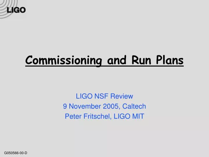
Commissioning and Run Plans. LIGO NSF Review 9 November 2005, Caltech Peter Fritschel, LIGO MIT. 2. 2. 2. 2. 4. 4. 4. 4. 1. 1. 1. 1. 3. 3. 3. 3. E3. E7. E5. E9. E10. E8. Runs. S1. S2. S3. S4. S5. Science. First Science Data. Commissioning and Running Time Line.

E N D
Commissioning and Run Plans LIGO NSF Review 9 November 2005, Caltech Peter Fritschel, LIGO MIT
2 2 2 2 4 4 4 4 1 1 1 1 3 3 3 3 E3 E7 E5 E9 E10 E8 Runs S1 S2 S3 S4 S5 Science First Science Data Commissioning and Running Time Line 2000 2001 2002 2003 2004 2005 2006 1999 2 4 2 4 4 1 3 1 3 2 4 3 1 3 Inauguration First Lock Full Lock all IFO Now 4K strain noise at 150 Hz [Hz-1/2] 10-21 10-22 4x10-23 10-17 10-18 10-20 E2 E11 Engineering
Major Achievements Since Last NSF Review • Factor of 2-3 (H1) to 6 (L1) improvement in sensitivity at 150Hz (noise minimum) • The 4km interferometers meet the Science Requirements Document (SRD) strain sensitivity goal of 10-21 rms in a 100 Hz bandwidth • Within 2 of the SRD example strain noise spectrum • Fixed absorption problem in H1 by replacing an ITM and cleaning the other • H1 & L1 use the full laser power available • S4 science run completed: sensitivity within a factor of 2 of goal; high duty cycle • S5 science run started: intended to produce 1 year of coincident data at design sensitivity
laser Interferometer optical layout vacuum H1: 4km @ LHO H2: 2km @ LHO L1: 4km @ LLO End test mass (ETM) suspended, seismically isolated test masses mode cleaner Input test mass (ITM) 4 km various optics 4-5 W 150-200 W 9-12 kW 10 W 6-7 W 200 mW photodetector Gravitational Wave channel
Sensitivity figure-of-merit: Inspiral Range Inspiral signal spectrum chirp mass angle factor SNR threshold strain noise psd • Inspiral FOM: • ρ = 8 • : binary of 1.4 M NS’s • Θ: averaged over directions and orientations; peak range a factor of 2.26 higher • Probes the ~octave band around the noise minimum • Not so sensitive to f > 200 Hz or f < 80 Hz Number of galaxies probed: in the hundreds example curve From astro-ph/0402091, Nutzman et al
The 4th Science Run • Dates (2005): • Start: 22 Feb • Stop: 23 Mar • Duty cycle: • H1: 80% • vs. 70% in S3 • L1: 74% • vs. 22% in S3: thanks to HEPI • H2: 81% • vs. 63% in S3 • Triple coincidence:57% • vs. 16% in S3 mid-run commissioning
Rms strain in 100 Hz BW: 0.8x10⁻²¹ S4 Sensitivity
Rms strain in 100 Hz BW: 0.4x10⁻²¹ Entering S5 … H2: 4.5 Mpc H1, L1: 10-11 Mpc
A brief history of HEPI 2001 Excess ground motion at LLO is characterized and quantified: rms in 1-3 Hz band is 5-15x bigger than at LHO Seismic upgrade effort is begun; req’s set, solutions explored. Design review: Apr ’02. External pre-isolator: 2 actuator types 2002 Fine tuning of control loops 2 prototypes built, installed & tested at MIT (LASTI): Quiet Hydraulic: BSC chamber Electro-magnetic: HAM chamber Hydraulic actuator selected: developed at Stanford for AdLIGO 2003 Production of HEPI mechanics and electronics 2004 S3 Installation & commissioning at LLO: Mar-Nov 2004 2005 S4: 74% duty cycle S5
Hydraulic External Pre-Isolator • The payload is supported by large coil springs, and actuated by quiet, high force hydraulic bridges. seismometer
The latest: reducing the stack modes X-arm length disturbance, noisy afternoon With HEPI in use, we expect the LLO detector to work on a typical noisy day, with at least a factor of 2 headroom. Locking threshold
Keys to high power operation • Thermal compensation system • Better alignment controls • Electronic suppression of orthogonal phase RF signal • Actually getting 10 W from the laser!
ITM Thermal Compensation System • Cold power recycling cavity is unstable: poor buildup and mode shape for the RF sidebands • Require 10’s of mW absorbed by 1μm beam for optimal thermal lensing • Can’t count on a specific level of 1μm beam absorption, so we provide our own: mask CO2 Laser ZnSe Viewport Over-heat pattern Inner radius = 4cm Outer radius =11cm Over-heat Correction Under-heat Correction
2 functions of the TCS Matching SB & carrier modes Symmetrizing the SBs to minimize the orthogonal-phase signal: controlling RF saturation CO2 heating Sideband images none carrier 90mW lower sideband Best match 180mW upper sideband
+ _ TCS in operation • Error signals developed for both degrees-of-freedom • Slow servos: ~10 min time constant • Common mode: • ‘bull’s-eye’ wavefront sensor • Compares carrier and SB modes in the recycling cavity • Set to maximize optical gain • Differential mode: • Minimize static component of AS port orthogonal phase signal • CO2 laser power levels: • H1: Central heating: 0-50 mW • H2: 75 mW central, 150 mW annulus • L1: 0-40 mW central, ~100 mW annulus
Alignment controls Transmission quads: 2 DOF, fix beam position on ETMs Optical levers: local reduction of angle fluctuations BW: 0.5-2 Hz Beam centering camera: fix beam position on BS (vertex) Wavefront sensors (WFS): 5 DOF Global alignment signals, BW: few Hz
Recent progress: WFS servo bandwidth increase • Complication: each sensor is sensitive, in general, to multiple mirrors • In the past, destabilizing interactions were avoided by keeping the servo bandwidths very low (except for WFS 1) • Now: mixing of control signals is carefully tuned to decouple the WFS channels from each other: 2A 2B WFS# 3 4 1 major element ETMX + + ETMY WFS control matrix minor element ITMX + ITMY RM 3-4 Hz 2 Hz 2 Hz 0.3 Hz 2 Hz Loop BW • Biggest benefit: reduces the orthogonal phase signal at the anti-symmetric port (ASI), allowing higher power operation
Laser power: woes & triumphs • 9 MOPA lasers purchased from LWE (’98-’99) • 10 W output in TEM00 mode • 10,000 hr mean-time-to-failure • Overall reliability has been good • Most lasers have 30,000+ hours • Several have been refurbished, a few repaired • L1: recent ups and downs • MOPA has been replaced 3 times since S4 • Optical efficiency from laser to mode cleaner significantly increased • Max input power 8 Watts in Aug ’05 • Lost ~20% from MOPA in Oct, now 6 W max • H2: original power amplifier lasted nearly 7 yrs • Replaced with refurbished in Sept • H1: refurbished laser installed Apr ‘04 • LWE acquired by JDSU, spring 2005 • Has delayed the repair of our lasers • Should be OK for S5 if refurbishment of another 3-4 lasers is done in a timely manner
H1: high absorption in the input test masses • S4: operated at 3 W input, with lots of TCS compensation • 1.5 W of annulus TCS power on ITMX (X arm): maxed out on CO2 laser power • Post-S4: carried out a program of in-situ characterization of optics • Arm cavity g-factor measurements: changes under thermal loading • Beam spot size changes • Absorption results: • ITMX: 35 mW/W, or about 20 ppm on the HR surface • ITMY: 13.5 mW/W, or about 8ppm on the HR surface Heat up with interferometer or TCS Measure change in spot size as ITM cools down Sensitivity: 5-10 mW absorbed • Post-S4: attempted to operate at higher input power, with more TCS • Bought & installed a higher power CO2 laser for ITMX
Dealing with H1 absorption • Strategy: gave until mid-June to achieve 10 Mpc sensitivity with the absorptive ITMX • 5-6 W into MC needed to achieve this • Hours long locks at 6 W achieved, but power levels not stable • No sensitivity improvement over S4 • Mid-June: decided to replace ITMX • Spare had been fully characterized at Caltech in the preceding months • Scattering, bulk & surface absorption, surface figure • Decided to also try in-situ cleaning of ITMY • Chamber vent took place on 29 June • Approx. 4 weeks of pumping before gate valves were opened
And now? • Interferometer has been run at 7 W into the mode cleaner • no annulus TCS needed • Absorption measurements repeated: • Forensics on the extracted ITM being carried out at Caltech • Appears to be due to point-like absorbers, rather than a uniform film • All in all, a very successful operation
Faster mechanical shutter just developed in-house: ~1 msec closing Preventing photodiode damage 5 msec • Loss-of-lock: full beamsplitter power can be dumped out the AS port, in a ~10 msec width pulse • Mechanical shutter cuts off the beam, with a trigger delay of about 6 msec • PD damage due to • Too high trigger level • Shutter too slow (wrong type) • Damaged PDs can be noisy • Solutions: • All shutters of proper type • Carefully set trigger level ~200 W Red: replaced damaged PDs
Noise Budget Noise budget and plot generated automatically
Low frequency noise not explained explained explained
Possible source:upconversion from stack motion Effect measured both at LHO & at LLO: Using HEPI, increase the suspension point motion at 1.5 Hz by a factor of 5 Noise increases significantly over a wide band H1 exhibits a day-to-night variation in low frequency noise, with a ~10% reduction in inspiral range during the day
Esc~10 -6 E0 Scattered light fringe wrapping ITM telescope ETM • Data looks a lot like what you’d expect from scattered light • Hard to account for the amount of scattered that seems to be needed • Don’t know where light is scattering off • Beam tube baffles were made for this purpose: 270 mm aperture • Not currently installed in the beam (laid down in beam tubes manifolds) • May erect ETM baffles some time during S5 • H1: recent efforts to reduce stack support point motion, using local feedback in 2 DOF
Other Commissioning Highlights • Post-S4: efforts to reduce H1-H2 correlated noise • 2 new acoustic enclosures for the REFLected port tables • Anti-Symmetric port table of H2 is ‘floated’ on pneumatic isolators • REFL port beam direction stabilization (L1, H1) • High-power induced deflection in the Faraday • Corrected with PZT-mirrors on the REFL table • Low noise oscillators for main modulation • Timing system upgraded on H2 • Distribution via fiber; better diagnostics • Reworked & wider bandwidth laser frequency & power stabilization loops • Photon calibrators in place as a calibration check
S5 run plan and outlook Interferometer duty cycles • Goal is to “collect at least a year’s data of coincident operation at the science goal sensitivity” • Expect S5 to last about 1.5 yrs • S5 will not be completely ‘hands-off’ • Expect to take 1-2 week breaks (every few months?) to make improvements; examples: • Beam tube baffles • Power increase steps: new PMC, new laser • Propagate timing system upgrade • Work on low frequency noise excess
Looking beyond S5: the next 5-6 Years Other interferometers in operation (Virgo) 4Q ‘06 4Q ‘07 4Q ‘08 4Q ‘09 4Q ‘10 4Q ‘05 • Between the end of S5 and the beginning of AdLIGO installation, there is some time for detector improvements • Sensitivity improvements that would pay-off more than continuing to run at S5 level • Implement and gain experience with technologies, techniques and subsystems that are part of the Adv LIGO design S5 ~2 years S6 Decomm IFO1
Improvements being considered • Output mode cleaner • In-vacuum implementation, could be DC readout • Possibly with AdLIGO HAM chamber seismic isolation • Higher power laser • Further amplify existing lasers • Possibly with Laser-Zentrum Hannover (LZH) AdLIGO technology • AdLIGO higher power optical components: Faradays, Electro-Optic Modulators • Seismic noise suppression
Recommendations from 2004 review • “As LIGO approaches the S5 science run, increased emphasis should be placed on improving the duty factors of the three interferometers.” • S4 much improved over S3; S4 was mined for sources of lock-loss • “It is important to address the reliability of laser operating power with the manufacturer Lightwave. A schedule for routine maintenance should be budgeted for and followed. Uncertainties in the source of the reduced mode-cleaner throughput should be identified, and if possible remedied.” • Laser status covered; mode-cleaner efficiency not addressed • “The thermal compensation system should be commissioned at the other interferometers as soon as possible, with further research continuing to allow the interferometers to reach their full laser power design goal by science run S5.” • Done, TCS implemented on all interferometers
Summary • Factor of 2 sensitivity improvement over the last year • Sensitivity goal achieved • S5 science run just beginning • End of commissioning-dominated phase of initial LIGO • Prospects for achieving duty cycle goals are good • Planning underway to make the best scientific use of the interferometers between the end of S5 and Advanced LIGO installation