Download
1 / 5
80 likes | 299 Views
Thin Lenses. If the thickness of the lens is small compared to the object and image distances we can neglect the thickness (t) of the lens. All thin lenses have two refracting surfaces, therefore we can combine the two expressions for each of the refracting surfaces. . Assuming .

E N D
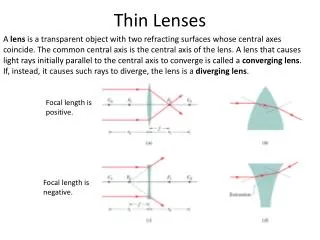
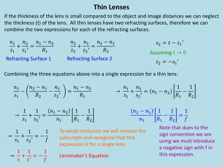
Thin Lenses If the thickness of the lens is small compared to the object and image distances we can neglect the thickness (t) of the lens. All thin lenses have two refracting surfaces, therefore we can combine the two expressions for each of the refracting surfaces. Assuming Refracting Surface 2 Refracting Surface 1 Combining the three equations above into a single expression for a thin lens: Note that dues to the sign convention we are using we must introduce a negative sign with f in this expression. To avoid confusion we will remove the subscripts and recognize that this expression is for a single lens. Lensmaker’s Equation
Thin Lenses: Thin lenses are constructed from two surfaces, which can be either concave, convex or flat. From geometry we can obtain an expression relating the object distance, image distance and focal point. We can also obtain an expression for magnification. Sign Convention - Lenses Object: Positive location – in front of lens (Real) Negative location – behind lens (Virtual) Image: Positive location – behind lens (Real) Negative location – in front of lens (Virtual) Positive height – upright (Same) Negative height – inverted Positive focal length – concave Negative focal length – convex Thin Lens Equation (valid only for thin lenses) Magnification These are the same relationships that were obtained for mirrors! The sign convention is different for lenses!
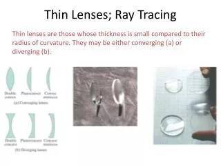
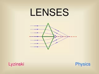
Lens Ray Diagrams Convex: 1) The incident ray is drawn parallel to the principle axis. The refracted ray passes through f2. f2 i 2) The incident ray is drawn so it passes through f1. The refracted ray is parallel to the principle axis. o f1 3) The incident ray is drawn through the center of the lens. The ray is not refracted an continues along a straight line path. Concave: 1) The incident ray is drawn parallel to the principle axis. The refracted ray passes through f1. o i f2 f1 2) The incident ray is drawn so it passes through f2. The refracted ray is parallel to the principle axis. 3) The incident ray is drawn through the center of the lens. The ray is not refracted an continues along a straight line path.
q1 q2 Biconvex Biconcave From the diagram above we can determine the magnification for a thin lens. This can also be accomplished using the diagram for the Biconvex lens. q The negative sign is from the sign conventions we are using. This is identical to what was done for mirrors.
Example: A system of two lenses is setup, where f1 = f2 = 15 cm, and the two lenses are separated by 60 cm. The object is located 25 cm in front of the first lens. The first lens in convex (biconvex) and the second is concave (biconcave). • Describe the image formed by the first lens. • Describe the image formed by the second lens. s1 = 25 cm f1 = -15 cm a) Real Image