Download
1 / 25
290 likes | 611 Views
PID Control Loops. Guy Zebrick. Contents . Open & Closed Loops Direct and Reverse Acting Proportional Control Integral Control Derivative Control Definitions Loop Tuning. Open Loop Control / Direct Acting. Mathematical Calculation. Input Control Variable. Setpoint. Output Device

E N D
PID Control Loops Guy Zebrick
Contents • Open & Closed Loops • Direct and Reverse Acting • Proportional Control • Integral Control • Derivative Control • Definitions • Loop Tuning
Open Loop Control / Direct Acting Mathematical Calculation Input Control Variable Setpoint Output Device 0-100% Input: Outside Air Temperature Setpoint: 50’F Output: Chiller on/off (0-100%) Action: Direct (input output )
Open Loop Control / Reverse Acting Mathematical Calculation Input Control Variable Setpoint Output Device 0-100% Input: Outside Air Temperature Setpoint: 60’F Output: Boiler on/off (0-100%) Action: Reverse (input output )
Closed Loop Control Reverse Acting Mathematical Calculation Input Control Variable Output Device 0-100% Setpoint Input: Room Temperature Setpoint: 70’F Output: Radiator Valve (0-100%)
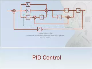
PID Control by Mathematical calculation Proportional Output varies in PROPORTION to input error Integral Output varies over TIME based on input error Derivative Output varies based RATE of CHANGE of input error P control P + I control P + I + D control (not used in our industry!)
PID closed loop control – driving at speed 0% P 30% PID 40% PI 60% PI 0% PID 40% PID 70% PI 25% PID 40% PI
Input Value Setpoint T1 T2 T3 T4 T5 T6 Time Definition: (SETPOINT) • The desired value of the input variable
Input Value Setpoint Offset T1 T2 T3 T4 T5 T6 Time Definition: OFFSET (error) • The DIFFERENCE between the input variable and the desired setpoint.
T1 T2 T3 T4 T5 T6 Definition: Throttling Range (Proportional Band) Amount of Change in INPUT that equals a 0-100% change in OUTPUT 100% ControllerOutput 50% 0% 70° 75° 65° Setpoint Throttling Range (Proportional Band) (10’F)
T1 T2 T3 T4 T5 T6 Proportional Control (with Offset Error) Control Point Setpoint Offset 0=100% Time
T1 T2 T3 T4 T5 T6 Proportional + Integral Control (eliminates offset) Control Point Setpoint Offset 0=100% Time
T1 T2 T3 T4 T5 T6 Derivative Calculation based on RATE of CHANGE Control Point Setpoint Offset D P + I + D Not used in our industry! Time
T1 T2 T3 T4 T5 T6 Integral Windup Condition Setpoint 100% Control Point Time Prevented by Disabling Loop when system is OFF
PID Enhancements • Setpoint Reset • Setpoint Recovery Ramp • Setpoint Demand Limit “BUMP” • Setpoint Select(s) • PID Output BIAS • PID Output Start Point • PID Output Start Ramp • PID Output Adjust Delay • PID Output Adjust Threshold • PID AUXILLARY Output • PID Output Sequencer
Definition: PID Output Bias 50% 0% 100% 100% 50% 50% 0% 0% T1 T2 T3 T4 T5 T6 T1 T2 T3 T4 T5 T6 Output = 50% at Setpoint Output = 0% at Setpoint
PID Setpoint RESET • Requires RESET sensor (typically outside air) • Automatically adjusts setpoint
PID Setpoint Recovery Ramp • Degrees/Hr • Requires multiple schedule information • Current State (occupied/unoccupied) • Next State (occupied/unoccupied) • Time until next state (minutes) UNOCC Setpoint OCC OCC Time
PID options (not available on ALL PID loops) • Output Start Value (%) • Provides starting value for initial control • Output Start Ramp (seconds) • limits action during initial startup to prevent overshoot • Output Dead Band (%) • Output Adjust Delay & Threshold • Prevents repeated minor adjustment to output • Prevents needless wear & tear on mechanical devices
T1 T2 T3 T4 T5 T6 Definition: Hunting (over-reacting) 100% ControllerOutput 50% 0% 70° Setpoint 69° 71° Proportional BandThrottling Range (2’F) Time
Tuning Hints: • PI control for closed-loop applications only. • The narrower (smaller) the throttling range, the more precise the control operation. The wider (larger) the throttling range, the more stable the control action. • Generally the throttling range required for PI control is greater than what is used for proportional control only. • The integral time value is set in seconds. A slow process such as space temperature control requires a long integral time (600 seconds or more), while a fast process such as static pressure control requires a short integral time. • An integral time of 0 eliminates the integral function for the control loop.
Typical Values From Engineering Manual • Default Space Temperature Control (CV AHU controller)
Field Tuning • Integral Time to Zero • Throttling Range = ½ Input Sensor Range • Adjust Throttling Range to point where about first begins to hunt. • Increase Throttling Range 1.5 X • Add Integral Time based on system response time • (typically 60 – 2500 seconds) • Check for Stable Operation
PID POP Quiz • Define open loop • Define closed loop • A cooling loop is (direct/reverse) acting • An AHU static pressure control loop is (direct/reverse) acting • Define P, I, D • Define throttling range • Define integral time • When do you use Differential control? • What adjustment(s) reduce ‘hunting’?