Download
1 / 48
490 likes | 646 Views
Roy van Pelt. Illustrative Volume Rendering on Consumer Graphics Hardware. Exam Committee: dr. A. Vilanova (BMT) dr. ir. H.M.M. van de Wetering (CSE) dr. ir. M. Chaudron (CSE). Project motivation. Improve comprehensibility Useful for context visualisations

E N D
Roy van Pelt Illustrative Volume RenderingonConsumer Graphics Hardware • Exam Committee: • dr. A. Vilanova (BMT) • dr. ir. H.M.M. van de Wetering (CSE) • dr. ir. M. Chaudron (CSE)
Project motivation • Improve comprehensibility • Useful for context visualisations • Similar to illustrations in physiology books
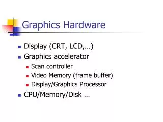
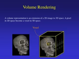
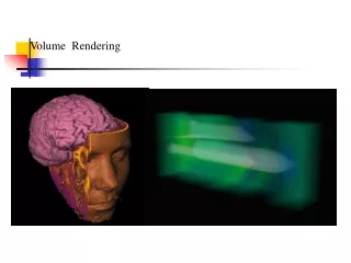
Introduction: Illustrative Volume Rendering • Volume Rendering • 3D dataset, i.e.: CT / MRI Images by kind courtesy of R. Brecheisen (2007) (MVR framework)
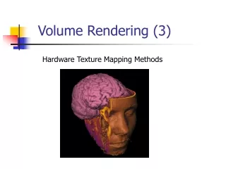
Introduction: Illustrative Volume Rendering • Illustrative Volume Rendering • Depict dataset as a drawing/sketch Stippling Hatching Contours
Introduction: Illustrative Volume Rendering • Existing framework: VolumeFlies • Traditional illustration techniques • Based on particle systems
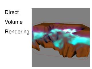
Project objectives • Design and implement VolumeFlies, using consumer graphics hardware, such that real-time interaction with the data is possible. • Integrate VolumeFlies with a direct volume rendering approach.
Background Info: GPU pipeline • Massively parallel • Adjust algorithms to use parallelism • Unified shader design • Programmability • Stream programming model using shaders Vertex Shader Geometry Processing Geometry Shader Rasterization Fragment Shader Fragment Operations
Vertex Shader Geometry Processing Geometry Shader Rasterization Fragment Shader Fragment Operations Background Info: GPU pipeline • Massively parallel • Adjust algorithms to use parallelism • Unified shader design • Programmability • Stream programming model using shaders
Background Info: General GPU approach Source buffer = “Input array” Destination buffer = “Output array” Vertex Shader Geometry Processing Geometry Shader Rasterization Fragment Shader Fragment Operations Transform feedback Discard fragment shader Proxy geometry = “Array index”
Background Info: Particle system • Particle: an element described by propertiesFor example particle position in the volume Movie source: http://www.runevision.com
1 2 3 4 Framework modules Initialises particle set Initialiser Behaviour Alters particle set Filter Removes unwanted particles Visualiser Illustratively depicts particles
1 Framework modules Initialiser Initialize particles near the ISO-surface Related to marching cubes
1 Framework modules Initialiser 3D Texture Volume Particle positions (x,y,z) = (r,g,b) Vertex Shader Geometry Shader Fragment Shader Proxy geometry
1 2 3 4 Framework modules Initialiser Behaviour Filter Visualiser
2 60 40 20 0.2 0.4 0.6 0.8 1 Framework modules Behaviour Minimise the total energy within the particle system Redistribute particles evenly on the surface Energy minimisation “Robust particle systems for curvature dependent sampling of implicit surfaces” – Meyer et al. (SMI 2005)
2 Framework modules Behaviour tangent plane iso-surface Redistribute particles evenly on the surface Two step particle displacement “Robust particle systems for curvature dependent sampling of implicit surfaces” – Meyer et al. (SMI 2005)
2 3 4 5 6 7 8 9 10 11 12 1 2 3 4 5 6 7 1 8 9 10 11 12 1 2 3 4 5 6 7 8 9 10 11 12 3 4 5 2 6 8 7 10 12 9 11 1 3 4 5 2 6 8 1 7 10 12 9 11 1 3 4 5 2 6 8 7 10 12 9 11 2 Framework modules Behaviour 1. Sort particles by their bin numberOdd-even merge sort Redistribution hard to port to GPU: Addressing all neighbours is computationally expensive Solution: Create a bin-structure to compute energy minimisation locally. 2. Create a lookup table for the binsBinary search 3. Redistribute particles by repulsionEnergy minimisation approach
2 Framework modules Behaviour Verify the change of the total energy Apply reduction operation on the GPU VolumeFlies applied a fixed number of iterations A new stop-criterion is introduced + + + Total system energy
2 Framework modules Behaviour Odd-Even Merge Sort Binary Search Energy Minimization Verify stop-criterion GPU approach more elaborate. Still much faster than CPU approach. Particle system is generic.
1 2 3 4 Framework modules Behaviour Initializer Filter Visualizer
3 Framework modules Filter a) Create the ISO surface Cone splatting: Cones directed to the viewing plane Cones are scaled to prevent edge overlap
3 Framework modules Filter b) Hidden surface removal Off-screen buffer: Splat rgb = Particle xyz Visible when particle position occurs as a colour
1 2 3 4 Framework modules Filter Initialiser Behaviour Visualiser
4 Density-based stippling Visualiser Per particle random threshold Based on basic diffuse lighting Vary particle density to change tone Initial density resembles darkest tone Executed by vertex shader User can control contrast
4 Scale-based stippling Visualiser Scale point representation Based on basic diffuse lighting Vary point size to change tone Larger points create darker areas Executed by vertex shader User can control contrast
4 Direction-based hatching Visualiser Single hatches Hatch tracing in a single direction Single and cross hatching Cross hatches
4 Direction-based hatching Visualiser iso-surface Hatch tracing in a single direction Segments projected in tangent plane
4 Direction-based hatching Visualiser Particle positions 3D Texture: Volume Hatch segments Vertex Shader Geometry Shader Fragment Shader 1 Proxy geometry Generate hatches in fixed direction Hatch segments Vertex Shader Geometry Shader Fragment Shader 2 Proxy geometry Visualise generated hatches
4 Direction-based hatching Visualiser 1st level 2nd level Again apply basic diffuse lighting Two-level threshold
4 Curvature-based hatching Visualiser Differential structure in volume required 1. Filtering approach for derivative reconstruction 2. Optimize for GPU by using interpolation capabilities Emphasize curvature with hatches Fast curvature calculation approach 3. Compute principal curvature “Fast Third-Order Texture Filtering” – Sigg, Hadwiger (GPU Gems 2) Re-implemented in high-level shading language Based on general GPU-approach
4 Curvature-based hatching Visualiser Variation of the normal vector when moving a small distance Maximum and minimum change describe the principal curvature Emphasize curvature with hatches Defining the principal curvature tangent plane iso-surface Image by Eric Gaba
4 Curvature-based hatching Visualiser • Measure first partial derivates: gradient • Measure second partial derivates: Hessian • Extract curvatures by eigen analysis on the shape operator Emphasize curvature with curvature Calculate principal curvature tangent plane iso-surface “Curvature-Based Transfer Functions for Direct Volume Rendering Methods and Applications” – Kindlmann et al. (IEEE Visualization 2003)
1D Transfer function 4 -1 0 1 Curvature-based hatching Visualiser
4 Curvature-based hatching Visualiser Messy hatch results using curvature directions Smooth the field directions and weight the trace Fixed direction when surface is unreliable
4 Curvature-based hatching Visualiser Principal curvature can be calculated in real-time Demonstrated by real-time curvature colour mapping
4 Contours Visualiser Contour: locations where normal is perpendicular to the view Draw ‘hatches’ for particles near the contour Segments trace the direction of the contour
Results: Performance Load Volume Brute-force initialiser 253.34 Redistribution Smooth Field 52.65 Hatch generation (Direction) 53.05 Hatch generation (Scale) Hatch visualisation Contours
Conclusions & Future work • Completely GPU-based • General GPU approach • Two generic components: • Particle system • Real-time curvature estimator • Integration with direct volume rendering • More elaborate memory management • Improvement of modules / Zooming • New applications and styles: DTI, animation, ghosting, exploded view…
Thank you for your attention! Questions?
Particle repulsion • Energy minimisation • Two step particle displacement
Stippling • Density-based • Scale-based
Hatching • Smooth field
Hatching • Tracing
Contours Image by D. DeCarlo
Curvature estimation 1/3 • Measure partial derivatives by convolution filtering with cubic B-spline
Weights lookup texture i-1 i i+1 i+2 x Colour texture Curvature estimation 2/3 • Optimise for the GPU by using interpolation
Curvature estimation 3/3 • Compute principal curvature • Eigen analysis on S


![Real-Time Volume Graphics [03] GPU-Based Volume Rendering](https://cdn2.slideserve.com/4026797/real-time-volume-graphics-03-gpu-based-volume-rendering-dt.jpg)