Download
1 / 52
520 likes | 684 Views
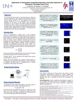
Simulation and Experimental Results of SSRF Top-up Operation. Haohu Li, Manzhou Zhang SSRF Top-up Workshop, Melbourne 2009.10.08. Contents. Brief introduction of SSRF Project Demands of top-up operation in SSRF Goal of top-up operation Requirements for top-up operation

E N D
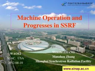
Simulation and Experimental Results of SSRF Top-up Operation Haohu Li, Manzhou Zhang SSRF Top-up Workshop, Melbourne 2009.10.08
Contents • Brief introduction of SSRF Project • Demands of top-up operation in SSRF • Goal of top-up operation • Requirements for top-up operation • Some simulation and experimental results • Summarize
Brief introduction of SSRF Project • SSRF is a third generation light source, the main parameters are as follows • Energy 3.5GeV • Circumference 432m • Effective Emittance ~4nm·rad • Beam Current 5mA(single bunch)/300mA(multi bunch) • Lifetime >10hours • Orbit Stability <10% of beam size • Straight Section sixteen 6.5m / four 12m
Machines In SSRF 3.5GeV Storage Ring C=432m Full Energy Booster C=180m 150MeV Linac
Lattice Parameters • 20 DBA cells, 4 superperiods • Four 12m long straight section used for • One for injection system • One for RF system • Others for users • Theoretical minimum emittance 1.5nm.rad • Norminal working point 22.22/11.29
Main Milestones during SSRF Construction • 2004.12.25 Ground breaking • 2007.05.15 First beam from LINAC • 2007.10.05 First 3.5GeV beam in booster • 2007.12.24 First stored beam (3GeV) in storage ring • 2008.01.03 Reached 100mA@3GeV • 2008.05.10 Light reached the end of the first beamline • 2008.09.30 Reached 200mA@3.5GeV • 2009.03.07 Light reached the end of the last beamline • 2009.05.06 Open to user • 2009.07.18 Reached 300mA@3.5GeV
Running status for users 595 people did 122 experiments in about 2 and a half months
Demands of Top-up Operation in SSRF • To provide more stable beam for users • Electron orbit stability, which we have already taken a lot of methods to keep the beam stabilized within 2~5 microns • Heating stabililty of beamline monochromator, which must be solved by keeping beam current as stable as possible, i.e. top-up injection • Beam current will oscillate within less than 1% level during top-up operation, that means the injection process will running frequently, mostly once per several minutes, and the users can still do experiment during this period.
Goal of top-up operation • Current stability • Single bunch <1% • Multibunch <0.1% • Orbit disturbance • Stored beam oscillation <0.1mm
Requirements of Top-up Operation • To achieve a good current stability, the system must have • High injection efficiency >99%
BP1 SP2-2 BP2 BEND KICK QF SP1 QD QD SP2-1 BP3 High injection efficiency • The injection efficiency of storage ring will be affected by the following conditions • Extraction beam property from booster • Injection system acceptance • Stored beam loss during injection • For the booster, digital power supplies are used to get a stable extraction beam’s energy, slow bump magnets (100ms) and high performance septa are helpful to increase the stability of the extraction orbit. • For the injection system of storage ring, we use collimators to limit the injection beam’s emittance, and this will also protect our insertion device with small gap. • For the stored beam, there should have no loss during injection, if the injection elements’ performance is good enough, because of its very small beam size, just 0.3mm for 1σx.
Injection efficiency of Storage ring • During injection, we measured the booster and storage ring’s dcct, injection efficiency >95% Booster DCCT 0.74mA ~0.444nC SR DCCT 0.3mA ~0.43nC
High injection efficiency • The injection efficiency of storage ring will be affected by the following conditions • Extraction beam property from booster • Injection system acceptance • Stored beam loss during injection • For the booster, digital power supplies are used to get a stable extraction beam’s energy, slow bump magnets (100ms) and high performance septa are helpful to increase the stability of the extraction orbit. • For the injection system of storage ring, we use collimators to limit the injection beam’s emittance, and this will also protect our insertion device with small gap. • For the stored beam, there should have no loss during injection, if the injection elements’ performance is good enough, because of its very small beam size, just 0.3mm for 1σx.
Collimator System • Collimator system is used to protect the elements, especially small-gap IDs. • Two collimators: horizontal and vertical • Location : inject straight section • Material : Ta • Thickness : 30mm(H)/60mm(V)
Horizontal Collimator Gap : ±14mm 95% of total lost beam are lost on the collimator
Vertical Collimator Without V Collimator 99.5% of total lost beam are lost on the collimator In-vacuum ID(cell 15) In-vacuum ID(cell 17) With V collimator, gap ±2.7mm
Experimental Results Vertical Lower Part Vertical Upper Part
Requirements of Top-up Operation • To achieve a good current stability, the system must have • High injection efficiency >99% • Sufficient long life time, >5 hours for single bunch and >10 hours for multibunch
Sufficient life time • For single bunch mode, the designed beam current is 5mA. Assume the lifetime is τ, the beam will lose 1% after τ*ln(1/0.99)=0.01 τ. When τ equal 5 hours, that means we must inject electron each 3 minutes. • For multibunch mode, the designed beam current is 300mA. In the same way, when life time equal 10 hours, the injection should be running each minute to reach ±0.1%.
Requirements of Top-up Operation • To achieve a good current stability, the system must have • High injection efficiency >99% • Sufficient long life time, >5 hours for single bunch and >10 hours for multibunch • Good diagnostic system for beam current, especially single bunch mode, at least 50 μA resolution. • The store beam orbit stability during injection is only depends on the injection elements’ performance, such as septum’s leakage field, kickers’ jitter, kickers’ field uniformity, and the difference between four kickers, etc.
Effects of Injection elements’ error • Errors • Timing jitter of kickers • Field reproducibility • Field uniformity • Installation misalignment • Injection beam mismatch • Leakage field of septa • …… • The first four types of errors will not only affect the injection beam, but also the stored beam. The fifth error will only affect the injection efficiency. The last one’s effect can be negligible with magnetic shielding layer on septum.
Timing jitter and field reproducibility of kickers • The horizontal emittance of the injection beam and the stored beam is about 110 nm·rad and 4~10 nm·rad, respectively, so the field instability will mostly affect the stored beam • The effective emittance will grow due to the power supply instability • If the amplitude of the kicker strength is θ0, the phase is φ0, and their errors are Δθi and Δφi, respectively, the subscript i represents different kicker, then we have
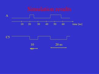
Timing jitter of kickers Right Figure: After injection process, store beam center position at the center of injection straight (timing jitter : 2ns, seed : 1000)
Timing jitter and field reproducibility of kickers 1000 seeds,3σ
Field uniformity of kickers • This error mainly comes from the metallic coating in ceramic vacuum chamber, because the kicker’s waveform width is very short, only 4μs. • From SLS kicker measuring result, when the average coating thickness is 3μm and waveform width is 6μs, the field uniformity will reduce to 2%, and this value is far less than 1%. • In SSRF, the average coating thickness is about 1.5 μm, and the waveform width is 4μs, the field uniformity will better than 3%. • This error is a system error, it will cause the stored beam disturbance, and can be reduced by adjusting their strength.
Simulation Results a = 2% a = 5%
Installation Misalignment • Only roll tolerance of kickers can effect on the stored beam, this is a system error, can not be reduced. • Assume the roll tolerance is 0.2mrad, 3σ,1000 seeds
Commissioning Results TBT data at BPM(1,2), where beta function is about 12m in both plane
Injection Beam Mismatch Injection efficiency with injection beam orbit error Injection efficiency with injection beam twiss parameter
Requirements of Top-up Operation • To achieve a good current stability, the system must have • High injection efficiency >99% • Sufficient long life time, >5 hours for single bunch and >10 hours for multibunch • Good diagnostic system for beam current, especially single bunch mode, at least 50 μA resolution. • The store beam orbit stability during injection is only depends on the injection elements’ performance, such as septum’s leakage field, kickers’ jitter, kickers’ field uniformity, and the difference between four kickers, etc. • The control system must be able to estimate when start and stop the injection process, which bucket need to be refill, and how many electrons need to be filled, etc.
Other considerations of top-up injection and operation • Control system • Running automatically • Reading beam current and comparing it with the current limit • Choosing buchet and setting timing system • Switching on/off the injection process • Send signal to users • Safety problem: Because the users will still work during injection, the safety of the optical elements must be very carefully studied. • Precise model of storage ring : the necessary condition for autocontrol during top-up operation
Problems • BPM offset will change with • Beam current • Bunch current distribution • Some unknown reasons
Filling Pattern After 12 hours Initial pattern
COD Difference between different filling pattern20 buckets vs. 40 buckets
COD Difference between different filling pattern100 buckets vs. 200 buckets
SOFB results on 2008.06.04 The last orbit difference with the initial value Total SOFB time: 5.5hours BPM number: 135 Eigen Values: 60/60 (H/V) Horizontal Vertical Orbit drift in the last 5.5 hours H V
SOFB results started from 2008.12.01 23:00, 14 hours 80个BPM Eigen values H : 40 V : 60
Effects of septum’s leakage field Septum 1&2 BPM2 of Cell 01~04 100 times TBT data