Download
1 / 22
230 likes | 660 Views
AD-R Series. Press Brakes. Optional Equipment. R Axis Back Gauge Manual Table Crowning Automatic Table Crowning Delem DA 56 Graphical Control Quick Release Punch Clamping Akas Ram Mounted Laser Operational Guarding Additional Finger Blocks 39” Back Gauge Hydraulic Tool Clamping

E N D
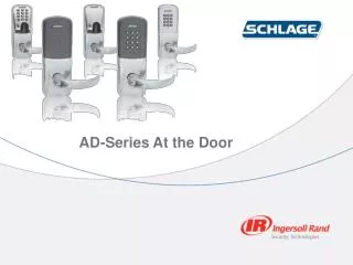
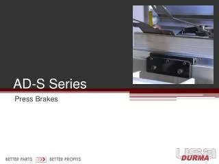
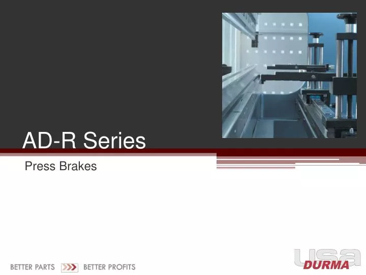
AD-R Series Press Brakes
Optional Equipment • R Axis Back Gauge • Manual Table Crowning • Automatic Table Crowning • Delem DA 56 Graphical Control • Quick Release Punch Clamping • Akas Ram Mounted Laser Operational Guarding • Additional Finger Blocks • 39” Back Gauge • Hydraulic Tool Clamping • Tooling Capacities Standard Equipment • 4’ – 20’ plus Tandem • 44 – 660 Tons • Y1, Y2 Servo Ram Positioning • X Axis Back Gauge with Fingertip Lateral Adjustment • Delem DA 52 Angle Programming • Quickset Front Sheet Supports via Linear Guide • Universal Wedge Style Punch Clamp for American or Euro Style Punches
High Engineering Standards Machine Frame Precision Machining The design of the machine frame is a critical part of any machine with relation to its ability to produce accurate parts for a long period of time. Durma uses several different types of construction, depending on the certain dimension, such as length, tonnage, stroke, daylight and throat/depth. Box frame construction is standard on machines 1,100-ton and larger. For details on Durma’s unique box frame construction, please reference the ADSL series. • Modern machining centers are utilized for accuracy, rigidity and smooth operation. Frames, assembly surfaces and connection holes are machined after the welding process, up to 60’ in a single pass. Surface machining nearly to grinding tolerance: 1.6-3.2 micron roughness average (0.8 micron on grinding). Parallel and square surfaces with 0.05-0.1 mm tolerances. There is no axial eccentricity. In comparison, non-precision machining results in: • Difference between Y1 Y2 (ram level) axes • Difficult to hold tools parallel • Difficult to hold tool dimensional tolerances • High vibration during the bending process
High Engineering Standards Cylinder Connection Ergonomic Working Height In order to allow tilting of the ram without damage, special spherical seating and connections are used. This type of connection also allows sudden forces to be absorbed gently. Lower beam (bed) height for most machines is optimized at approximately 35-36” (excluding die holders and dies) for ergonomic operation.
High Engineering Standards Lower Deflection & Longer Lifetime • Durma’s high engineering standards minimize stress and deflection. All mainframe components (side frames, ram, bed) are designed with built-in safety factors. All Durma machines are constructed from st44-2 steel. Acceptable industry stress standards for material is 8.5kg/mm2 stress. AllDurma machines must meet a value of 5-6kg/mm2. These strict standards reduce deflection and increase frame durability and the ability to hold tolerances over long periods of heavy use. All incoming plate must be certified by the Durma standards and requirements. Durma’s high frame rigidity and robustness provides long-term accurate bending. • What happens if lower engineering criteria are accepted? • For example, in the case of 8.5kg/mm2: • Weight of machine can be reduced by as much as 30% • Machine operates at limit for deflection and stress • Steel fatigues from high deformation and stress at limit, as well as the risk of cracking is present • High deflections on the ram and the bed that are too large to offset with crowning devices
High Engineering Standards Frame Welding • Welding methods are selected after “welding equivalent” calculation. • MIG MAG welding on frame (below right) • SAW (submerged arc welding – below left) at cylinder connection point. Welding at critical areas is subjected to high forces and vibration, and has to be clear of atmospheric contamination during the welding process. • Applied force at the welding position yields rigidity and strength.
High Engineering Standards Large Part Clearance A combination of the specially-designed reservoir, outboard mounted ram guides, large side frame gaps, strokes and daylights provide for increased openings and reduced collisions during the bending process.
Features Quick-Set Front Sheet Supports Y1, Y2 Precision & Flexibility Rugged support arms with disappearing stops are mounted on a linear guide rail system. This allows “fingertip” lateral adjustment as required by the bend length of the part. They are also equipped with side gauges for the fast, easy and accurate feeding of parts: small or large. • In the ADS Series, Y1, Y2 ram positioning system, each cylinder operates independently in a closed loop system. Linear encoders combined with precision hydraulic valves and the CNC command center provide +/- 0.0004” accuracy and the ability to program all ram position, speeds and ram tilt. Application advantages include: • Stage or progressive bending • Fade out or conical work • Enhanced material handling with total ram control
Features Large Stroke, Daylight & Throat Oversized Ram Guides • The large frame dimensions allow versatile production of parts requiring increased clearance profitably and easily. • Forming of deep sectioned four-sided boxes • Forming and removal of complex large parts Long, rectangular shaped guides assure stable, smooth and secure ram positioning. Conventional machines typically have these guides mounted on the inside of the frames, resulting in obstructions to the full length acute angle bends.
Features Universal Box Forming Style Punch Clamps Back Gauge X axis (finger depth) is set automatically via the program. The fingers are mounted on a linear guide for quick, easy, and accurate lateral positioning. A hand crank is located at the top of each finger for height adjustment. Programmable R axis (finger height) is optional. Up to 245 tons. A universal wedge style punch clamp accepts either American or European style punches. Because of their deep sectioned characteristics, they are very useful in deep box forming. The ability to form deep boxes with standard height punches is allowed. The yare designed with an integrated wedge that allows vertical adjustment due to tool or ram.
Air Bending Force T = Material Thickness V = V Opening MF = Minimum Flange Length IR = Inside Radius * Based on bending to an included angle of 88°. This dimension will increase when bending to an included angle of less than 88°. A36 steel requires a safety multiplier of 1.33 (80,000 PSI) to the chart. The bending force (tonnage) figures listed above are based on mild steel with tensile strength of 60,000 PSI. To calculate the approximate bending force requirements for other materials, please use the following multipliers: Soft Brass Tons Per Foot x 50% Soft Aluminum Tons Per Foot x 50% Heat Treated Aluminum Tons Per Foot x 100% Stainless Steel Tons Per Foot x 150%
Control Delem DA 52 • The Delem DA 52 control features quick, one-page programming and hotkey navigation. With a 6.4” VGA color LCD, the DA 52 controls up to 4 axes (Y1, Y2 and 2 auxiliary axes) and advanced Y-axis algorithms for closed loop as well as open loop valves. The DA 52 includes: • Crowning control • Tool/material/product library with 30 punches and 30 dies • USB, peripheral interfacing with data back-up/restoration • Panel-based controller with optional housing • Synchronized/conventional press brake control • 266 MHz processor, 64 MB memory • Product memory min. 2 MB • Power-down memorization • 7-digit program number • 20-character drawing number • Stock counter (up to 9999) • Step repetition (up to 99) • Millimeter / inch • One-page programming table • ‘Teach-in’ on all axes • Programmable axis speed per step • Programmable material properties • Graphic viewing is not possible on the standard DA 52 control.
Optional Control Delem DA 56 • The DA 56 provides graphical bend sequence calculation from very basic program info: tooling, bend angle and flange length. This allows the operator to see how the part is sequenced prior to bending. Other features include: • 2D graphical programming • 10.4” color LCD TFT display alpha numeric programming • Bend sequence determination • Stretch length calculation (blank size) • USB port for storage and back-up • 2BM product and tool memory • Graphic tool memory • Auto bumping • Angle correction database • 3D viewing is not possible on the DA 56 control.
Software Profile-on-Windows GUI 1-to-1 compatible with DA 65W, DA 66W and DA 69W Basic package W2D graphical like DA 65W/66W Extra option to W3D graphical like DA 69W Software upgrades parallel to DA 65W/66W/69W versions Easy import of Delem control settings Printing functionality of products and tools Versions Profile W2D • Graphical product drawing • Tool drawing 2D • 2D bend sequence calculation • 3D machine set-up / tool stations • Profile W3D • Additional 3D product drawing • 3D full automatic bend sequence calculation
Optional Features Shimless Bending X/R Style Back Gauge Both manual and automatic controlled crowning systems are available. The manual style is equipped with single point adjustment and position readout. In the case of the CNC type, the setting is automatically calculated and set from normal program information. Different than manual crowning, the position is automatically set via CNC. With the X/R style back gauge, the height of the back gauge is programmable in addition to the depth. This is very useful for changes in die height, extreme crowning settings, and for gauging to the flange that may be a different height than the die.
Optional Features Safety Due to the multiple purpose use of press brakes, point of operation guarding is the responsibility of the machine buyer/user. For this reason we offer the Akas ram mounted “laser” style point of operation guard. The system is based off the location of the punch tip. Simply by pressing a button the system travels down and finds the safe setting relevant to the punch being used at the time.
Optional Features Z1, Z2 Independent Finger Width X1, X2 Independent Finger Width Independent finger width movements allow gauging of stage or progressive work along the bed and also automatically set according to bend length or part width. Allows gauging of parts requiring a large taper. Fingers are mounted on a common gauge bar.
Tooling and Tool Clamping Durma Laser Hardened Tooling Precision Ground Euro-Style Tool Package Lever-Style Quick Release Punch Clamp Typical machines 350 tons and over are equipped as standard with an American-style punch clamp and a large multi-vee table with five or more vee-openings. The opening sizes are dependent on the machine tonnage. • A very flexible and affordable precision ground tolling package is available. It consists of a four-way bottom die with openings: • 0.625” / 88° • 1.37” / 85° • 1.96” / 85° • 0.030” / 75° • A four-way die holder is also included. The longest punch or die is 32” long. A push-pull lever eliminates the need for loosening and tightening bolts for punch removal. This style does not allow vertical loading/unloading of tolls with safety tang. Available for Euro-style punches and is not self-seating.
Tooling and Tool Clamping New Standard Style Hydraulic Die Clamping American Style Tooling New Standard concept is also available. This concept is generally a little harder and utilizes the patented “hour glass” tang for self-seating. Hydraulic die clamping provides an equally fast method of securing the lower dies. It is available for both American and News Standard style dies. Both precision ground and sectionalized tooling, as well as conventional full length style tooling, is available.
Tooling and Tool Clamping Durma Hydraulic Punch Clamping Hydraulic Punch Clamping Patented ‘easy slide’ removal of the punch. Built to withstand loads up to 330 tons per foot for demanding jobs with heavy load over short area. We offer several styles of hydraulic punch clamping. Each automatically centers and seats the punch and allows vertical removal support. Setup times can be dramatically reduced. It is available for American and New Standard style concepts.
Learn More Datasheets View Online Printer-Friendly Version
Durma Aims for Continuous Development DURMA’s large investment in machining centers and production equipment, as well as its ISO-certified factories totaling 1,350,000 square feet and 1,000 employees, make one of the world’s largest, efficient and most contemporary facilities in the world. In order to offer customer solutions and further develop patents, the DURMA Research and Development center opened in 2010. Fifty engineers were added over the last two years. Designed and engineered with modern technology, DURMA products are equipped with high quality and proven readily available components. Established in 1956, DURMA has vast experience in building and supplying quality products. With over 60,000 machines delivered worldwide, DURMA has earned the reputation as a supplier of innovative, “value oriented” solutions. Your partner today, tomorrow and forever.