Download
1 / 35
380 likes | 434 Views
Transport in Plasma Edge and Scrape Off Layer. Nicola Bonanomi. NOTA. Presentation based on: F. Militello , Culham summer school lecture on edge and SOL transport, Culham 2015; D . A. D’Ippolito , J . R. Myra and S. J. Zweben , Physics of Plasmas 18, 2011

E N D
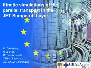
Transport in Plasma Edge and Scrape Off Layer Nicola Bonanomi
NOTA • Presentation based on: • F. Militello, Culham summer school lecture on edge and SOL transport, Culham 2015; • D. A. D’Ippolito,J. R. Myraand S. J. Zweben, Physics of Plasmas 18, 2011 • Howard Wilson, Edge localized modes in tokamaks, Carolus Magnus summer school, Leuven 2015 • L. Easy et al., 57th Annual Meeting of the APS Division of Plasma Physics, 18/11/2015
OVERVIEW • Edge/SOL transport • Filaments and ELMs • Filaments and “blob” theories • Conclusions
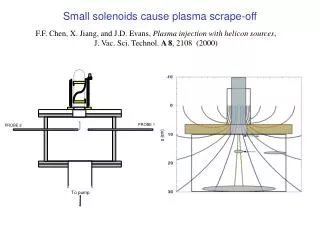
Where are the Edge and the Scrape Off Layer ? Field lines are open in the SOL • Parallel fluxes to the divertor
Edge v/s Scrape Off Layer v/s Core • CORE: • Higher density and temperature • Te~10 kev • ne~1019 m-3 • Lower collisionality • EDGE: • Colder and more rarefied than core • Neutrals • SOL: • Open field lines • Plasma-Surface Interaction • Atomic Processes • Te~102ev • ne~1019 m-3 • Collisions and electromagnetic effects are important in EDGE and SOL
Why study the transport in EDGE and SOL • Wall – Engineering: • It determines the erosion of the plasma facing components • It sets the heat loads on the walls • and the divertor • Plasma Physics: • Pedestal formation --> L-H transition • ELMs • Its physics determines the density limit • ITER: to avoid significant damages and to improve the performances we need to understand the edge physics to control its behavior
Transport in EDGE/SOL • Diffusive transport • Localrelationship between equilibrium gradients and turbulent fluxes • Gaussian statistics CORE: EDGE/SOL:
Transport in EDGE/SOL, NONLOCALITY The transport mechanism is non local: thegradients that create the transport can be quite far from the location where the transport is measured!
Transport in EDGE/SOL, INTERMITTENCY • Evidence for intermittency in the SOL measured experimentally and in numerical sim. • The Edge is almost Gaussian (i.e. dominated by uncorrelated events)
Transport in EDGE/SOL, FILAMENTS FROM BOTH EXPERIMENTS AND SIMULATIONS: • Nonlinear relation between fluxes and gradients --> NONLOCALITY • Large fluctuations • Non-Gaussian statistics --> INTERMITTENCY These observations suggest the presence of coherent structures: BLOB/FILAMENTS --> Blobs/Filament of plasma detach from the edge and travel in the SOL to the divertor The SOL is characterized by an intermittent behavior, with large random events generated elsewhere
BLOB/FILAMENTS • This is a field of active research, what follow is speculative! • The filaments are born in the Edge • The generation mechanism of the filaments is different in L-mode and H-mode • In L-mode the best candidate is drift-wave turbulences • In H-mode the filaments are the nonlinear phase of an ELM event
OVERVIEW • Edge/SOL transport: filaments • Filaments and ELMs • Filaments and “blob” theories • Conclusions
Filaments - ELMs (Edge Localized Modes) In H-mode the filaments are likely to be generated by nonlinear evolution of ELMs. --> ELM detected by observing the emission of D light near the divertor target plates. D light is emitted from the divertortarget plate region due to the electrons ejected from the core plasma during the ELM interacting with neutral particles • --> Different kinds of ELMs: • Type I: low frequency and high energy ejected • Grassy ELMs: higher frequency and lower energy ejected • Type III, Type II.. • Dependence on plasma parameters
Filaments - Peeling-Ballooning mode --> The peeling-ballooning model (ideal MHD) has emerged as the strongest contender to explain the characteristics of the largest ELMs: Type I --> The model derives from two particular instabilities: the ballooning mode and the peeling mode • Ballooning mode: • Short wavelength perpendicular and long wavelength parallel to the magnetic field • Destabilized when the pressure gradient exceeds a critical value • Stabilized by current density • Sufficiently high current density completely stabilizes the ballooning mode • Localized on the LFS (Low Field Side) • Peeling mode: • Destabilized by the current density at the plasma edge • Stabilized by pressure gradient • Strongly related to the external kink instability • Highly localized: only affects a very small region of the transport barrier, exceedingly close to the plasma edge
The Peeling-Ballooning mode --> At high pressure gradient, the peeling and ballooning modes couple: strong instability with both current and pressure gradient drives that affects the whole transport barrier region. It is this coupled instability that is thought to be responsible for driving Type I ELMs. Coupling region LFS Picture of the Peeling-Balooning instability from simulations
ELMs from peeling-ballooning mode Possible trajectories for the edge pressure gradient and current density in an ELMingdischarge. Trajectory 1 (proposed for Type I ELM):. Plasma stable between ELMs: edge pressure gradient increases up to the ballooning boundary. Bootstrap current (proportional to the pressure gradient) also increase until the peeling-ballooning mode is destabilized. Instability develops, the pressure gradient fall destabilizing the mode and triggering a large crash in the pressure (and consequent large energy loss). The discharge parameters eventually re-enter the stable region, and the cycle repeats.
Peeling-ballooning, NONLINEAR theory --> Linear models ~ quantitative informationabout the onset of instability: cannot explain the energy ejected during an ELMs • --> Non-linear theory: • The mode amplitude grows is accelerated much above the linear growth rate • Spatial structure of the mode altered to form filament-like structures aligned with the magnetic field line
Peeling-ballooning, NONLINEAR theory • --> The explosive growth predicted suggests that it is possible to trigger a crash event just by considering the ballooning mode • --> Key term that causes the explosive behavior: if the coefficient of this term is positive, the filaments erupt outwards towards the scrape-off layer, otherwise they erupt inwards towards the core • --> The filaments only erupt outwards when there is sufficient current density in the plasma edge. If one assumes that an outwarderuptingfilament is more dangerous than an inward one, then this could provide another reason why the ELM size might depend on the edge current density and provide an ingredient to understanding the differences between the mechanisms for large and small ELMs. • --> The filament remains connected into the core plasma on the inboard side. Thus the filaments due to a non-linear ballooning mode can continue to tap the free energy of the pressure gradient in the transport barrier, and accelerate rapidly away from the core plasma. In addition, because they remain connected to the core plasma, they can act as a conduit (or hose-pipe), linking the transport barrier region to the scrape-off layer, siphoning hot plasma from the barrier region into the exhaust region.
ELMs heat loss mechanis • Peeling-Ballooning theory described with ideal MHD cannot exlain heat loss mechanisms • 3 mechanisms proposed: • Leaks from the filaments • Reconnection near the X-point: the magnetic field lines contained in the hot filament break and then reconnect with the magnetic field lines of the scrape-off layer on the outboard side. Because the filament is relatively unperturbed on the inboard side, it remains inside the transport barrier there. Thus, following the reconnection event, there would be a continuous path along the filament from the pedestal region to the divertortarget plates, and therefore a rapid loss of heat and particles • The transport barrier is thought to be sustained by sheared plasma flow within it. As the filament pushes out, it suppresses the flow shear and the barrier collapses with a significant, temporary confinement degradation
OVERVIEW • Edge/SOL transport • Filaments and ELMs • Filaments and “blob” theories • Conclusions
“BLOB” theories • --> The turbulence in the Edge is produced by interacting drift-waves • --> The magnetic field enforces an asymmetric behavior for the turbulence, which becomes quasi-2D and tends to generate structures • BLOB FORMATION • --> The system undergoes a sub-critical bifurcation • --> Filaments created by nonlinear saturation of drift-waves instabilities
Structure of blobs F vF~ q It has a monopole (single-peaked) density distribution with a peak value much higher than the surrounding rms fluctuations of the background plasma (typically 2–3 times higher) It is aligned parallel to the magnetic field B and its variation along B is much weaker than in the transverse direction It has a dominant convective ExBvelocity component in the direction of a charge-polarizing force, and an associated potential and vorticity with a dipole structure E vExB (B // z)
Structure of blobs --> Force (~ grad(n)) cause a drift that cause charge separation --> Electric field: E x B motions move the filament radially --> Density profile depend on the background density: reduces the drive for the blob velocity and alters the structure of the blob: the interaction of the blob with the background density produces a sheared flow pattern which leads to the formation of a steep leading edge and trailing wake Target
Dynamics of filaments Because blobs are radially convecting structures, they will transport all plasma properties, including particles, heat, momentum and parallel current --> need to know its dynamic Once the filament detaches from the core region, its dynamic becomes ballistic: it is driven by its own field and pressure gradients The filament has a ballooning structure: it expands in the parallel direction as it moves radially. The balance between parallel and perpendicular dynamics sets the width of the SOL
Parallel dynamics The parallel dynamics can be seen as a vacuum expansion: ambipolaritydetermines the dynamics
Perpendicular dynamics In the perpendicular direction the filament propels itself through a self-generated ExBdrift Polarisation Diamagnetic Parallel To evaluate the perpendicular velocity of the filament, we can use a simple fluid model. Quasi-neutrality implies: Balancing different terms in this equation, we find different scalings for the filament velocity
Perpendicular dynamics • Charge polarization --> constant current source • The effective resistivity of the circuit determines the vertical potential difference across the blob and the resulting radial velocity • High resistivity: path of least resistance perpendicular to the field lines and the circuit closes in the divertor region. A blob that has a circular cross-section at the midplane is stretched into a thin ellipse (even ~ ion gyroradius in thickness) near the X-point by the magnetic field line mapping --> a perpendicular current can easily flow across the thin dimension of the blob, dropping the effective resistance of the blob circuit. The blob current loop can be closed at the X-point by the perpendicular ion polarization current or by collisional electron currents • Low resistivity:, the current flows unimpeded along the field lines from the midplane to the sheath at the end plate, and the blob velocity is determined by the sheath resistivity Filament Target Inertially Limited Sheath Current Limited
Perpendicular dynamics - resistivity Suppression of Parallel currents Resistivity enhanced in last 25% of domain nearest target Increasing Resistivity Midplane Target
Filaments, transport • The fraction of heat and particles that the filament deposits on the wall or on the divertor depends on the plasma regime. • In standard operation, most of the fluxes go to the divertor. • The amount of flux that reaches the walls depends on the line averaged density (or what else?) • Linked to the density limit?
Blobs, experimental evidences • --> SOL fluctuations provide an abundant source of experimental data for statistical analysis. An important result from the statistical analysis of SOL fluctuations is their intermittent and non-Gaussian character. • Probability distribution function (PDF): probability that a fluctuating quantity lies in a certain position in space • Theskewness(S) measuresthepositive-negativeasymmetry of the PDF, and thekurtosis (K) measureswhetherthedistributionis more peakedorflatterthan a normal distribution • From S and K the intermittency of some events can be quantify
Blobs, experimental evidences Evidence for intermittency in the SOL measured in TEXTOR and in numerical studies. The Edge is almost Gaussian (i.e. dominated by uncorrelated events), while the SOL shows an high Kurtosis indicating intermittent activity. Propagation of blob filaments provides a mechanism for explaining the spatial and temporal intermittency (large positive skewness and kurtosis) and the non-Gaussian PDF of fluctuations observed in the SOL of edge turbulence simulations and experiments
Blobs, experimental evidences Blob creation and propagation in NSTX. The image frame rate is 7.5 10-6 s/frame and the field of view is 25x25 cm near the outer midplaneseparatrix (solid line). This bright blob forms near the separatrix and moves radially outward toward the limiter shadow (dashed line) at 1 km/s.
Conclusions ITER steady state: max 10 MW/m2 on divertorand 5 MW/m2 on wall --> UNDERSTAND AND CONTROL the fluxes at the Edge/SOL is essential for the operations in a fusion reactor