Download
1 / 25
250 likes | 375 Views
PART 4 Computer Model. Basic Components LC-3 Instruction Cycle Execution Control. The Stored Program Computer. 1943: ENIAC Presper Eckert and John Mauchly -- first general electronic computer. (or was it John V. Atananasoff in 1939?) Hard-wired program -- settings of dials and switches.

E N D
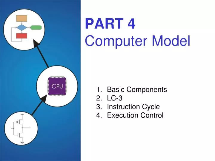
PART 4Computer Model • Basic Components • LC-3 • Instruction Cycle • Execution Control
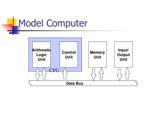
The Stored Program Computer 1943: ENIAC • Presper Eckert and John Mauchly -- first general electronic computer.(or was it John V. Atananasoff in 1939?) • Hard-wired program -- settings of dials and switches. 1944: Beginnings of EDVAC • among other improvements, includes program stored in memory 1945: John von Neumann • wrote a report on the stored program concept, known as the First Draft of a Report on EDVAC The basic structure proposed in the draft became knownas the “von Neumann machine” (or model). • a memory, containing instructions and data • a processing unit, for performing arithmetic and logical operations • a control unit, for interpreting instructions For more history, see http://www.maxmon.com/history.htm
Contents 00101101 • • • 10100010 Memory k x m array of stored bits (k is usually 2n) Address • unique (n-bit) identifier of location Contents • m-bit value stored in location Basic Operations: LOAD • read a value from a memory location STORE • write a value to a memory location Address 0000 0001 0010 0011 0100 0101 0110 1101 1110 1111
Interface to Memory How does processing unit get data to/from memory? To read a location (A): To write a value (X) to a location (A): MAR: Memory Address Register MDR: Memory Data Register • Write the address (A) into the MAR. • Send a “read” signal to the memory. • Read the data from MDR. • Write the data (X) to the MDR. • Write the address (A) into the MAR. • Send a “write” signal to the memory.
Processing Unit Functional Units • ALU = Arithmetic and Logic Unit • could have many functional units.some of them special-purpose(multiply, square root, …) • LC-3 performs ADD, AND, NOT Registers • Small, temporary storage • Operands and results of functional units • LC-3 has eight register (R0, …, R7) Word Size • number of bits normally processed by ALU in one instruction • also width of registers • LC-3 is 16 bits
Input and Output Devices for getting data into and out of computer memory Each device has its own interface,usually a set of registers like thememory’s MAR and MDR • LC-3 supports keyboard (input) and console (output) • keyboard: data register (KBDR) and status register (KBSR) • console: data register (CRTDR) and status register (CRTSR) Some devices provide both input and output • disk, network Program that controls access to a device is usually called a driver.
Control Unit Orchestrates execution of the program Instruction Register (IR) contains the current instruction. Program Counter (PC) contains the address of the next instruction to be executed. Control unit: • reads an instruction from memory • the instruction’s address is in the PC • interprets the instruction, generating signals that tell the other components what to do • an instruction may take manymachine cycles to complete
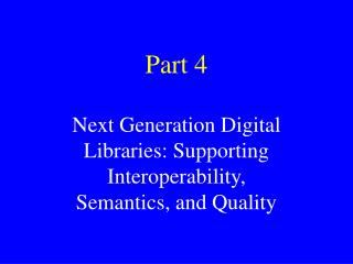
Instruction Processing Instruction Processing Fetch instruction from memory Decode instruction Evaluate address Fetch operands from memory Execute operation Store result
Instruction The instruction is the fundamental unit of work. Specifies two things: • opcode: operation to be performed • operands: data/locations to be used for operation An instruction is encoded as a sequence of bits. (Just like data!) • Often, but not always, instructions have a fixed length,such as 16 or 32 bits. • Control unit interprets instruction:generates sequence of control signals to carry out operation. • Operation is either executed completely, or not at all. A computer’s instructions and their formats is known as itsInstruction Set Architecture (ISA).
Example: LC-3 ADD Instruction LC-3 has 16-bit instructions. • Each instruction has afour-bit opcode, bits [15:12]. LC-3 has eight registers (R0-R7) for temporary storage. • Sources and destination of ADD are registers. “Add the contents of R2 to the contents of R6,and store the result in R6.”
Example: LC-3 LDR Instruction Load instruction -- reads data from memory Base + offset mode: • add offset to base register -- result is memory address • load from memory address into destination register “Add the value 6 to the contents of R3 to form amemory address. Load the contents stored inthat address to R2.”
Instruction Processing: FETCH Load next instruction (at address stored in PC) from memoryinto Instruction Register (IR). • Load contents of PC into MAR. • Send “read” signal to memory. • Read contents of MDR, store in IR. Then increment PC, so that it points to the next instruction in sequence. • PC becomes PC+1. F D EA OP EX S
Instruction Processing: DECODE First identify the opcode. • In LC-3, this is always the first four bits of instruction. • A 4-to-16 decoder asserts a control line correspondingto the desired opcode. Depending on opcode, identify other operands from the remaining bits. • Example: • for LDR, last six bits is offset • for ADD, last three bits is source operand #2 F D EA OP EX S
Instruction Processing: EVALUATE ADDRESS For instructions that require memory access,compute address used for access. Examples: • add offset to base register (as in LDR) • add offset to PC (or to part of PC) • add offset to zero F D EA OP EX S
Instruction Processing: FETCH OPERANDS Obtain source operands needed to perform operation. Examples: • load data from memory (LDR) • read data from register file (ADD) F D EA OP EX S
Instruction Processing: EXECUTE Perform the operation, using the source operands. Examples: • send operands to ALU and assert ADD signal • do nothing (e.g., for loads and stores) F D EA OP EX S
Instruction Processing: STORE Write results to destination.(register or memory) Examples: • result of ADD is placed in destination register • result of memory load is placed in destination register • for store instruction, data is stored to memory • write address to MAR, data to MDR • assert WRITE signal to memory F D EA OP EX S
Changing the Sequence of Instructions In the FETCH phase,we incremented the Program Counter by 1. What if we don’t want to always execute the instructionthat follows this one? • examples: loop, if-then, function call Need special instructions that change the contents of the PC. These are called jumps and branches. • jumps are unconditional -- they always change the PC • branches are conditional -- they change the PC only ifsome condition is true (e.g., the contents of a register is zero)
Example: LC-3 JMPR Instruction Set the PC to the value obtained by adding an offsetto a register. This becomes the address of the next instruction to fetch. “Add the value of 6 to the contents of R3,and load the result into the PC.”
Instruction Processing Summary Instructions look just like data -- it’s all interpretation. Three basic kinds of instructions: • computational instructions (ADD, AND, …) • data movement instructions (LD, ST, …) • control instructions (JMP, BRnz, …) Six basic phases of instruction processing: F D EA OP EX S • not all phases are needed by every instruction • phases may take variable number of machine cycles
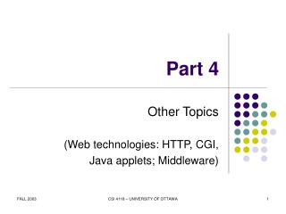
“1” “0” Machine Cycle time Driving Force: The Clock The clock is a signal that keeps the control unit moving. • At each clock “tick,” control unit moves to the nextmachine cycle -- may be next instruction ornext phase of current instruction. Clock generator circuit: • Based on crystal oscillator • Generates regular sequence of “0” and “1” logic levels • Clock cycle (or machine cycle) -- rising edge to rising edge
Instructions vs. Clock Cycles MIPS vs. MHz • MIPS =millions of instructions per second • MHz =millions of clock cycles per second These are not the same -- why? --MIPS stands for millions of instructions can execute by processor per second. you don't know what these instructions are doing --MHZ tells you how fast a clock is for a given processor. It doesn't tell you what is happening during those clocks
Stopping the Clock Control unit will repeat instruction processing sequenceas long as clock is running. • If not processing instructions from your application,then it is processing instructions from the Operating System (OS). • The OS is a special program that manages processorand other resources. To stop the computer: • AND the clock generator signal with ZERO • when control unit stops seeing the CLOCK signal, it stops processing
Exercise 4 • 4.3 • 4.7 • 4.8 • 4.10 • 4.16