Download
1 / 17
170 likes | 318 Views
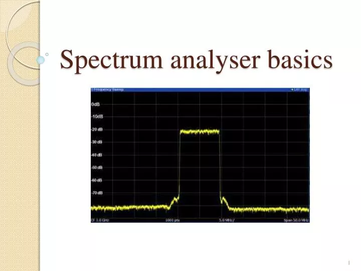
Spectrum analyser basics . Functionality . Analyse the frequency spectrum of a radio frequency signal. Display the spectrum in the format of amplitude (vertical) vs. frequency (horizontal) axes. Many telecoms applications, e.g. transmitter monitoring for interference avoidance. .

E N D
Functionality • Analyse the frequency spectrum of a radio frequency signal. • Display the spectrum in the format of amplitude (vertical) vs. frequency (horizontal) axes. • Many telecoms applications, e.g. transmitter monitoring for interference avoidance.
Types -Swept-tuned: sweep the frequency that is analysedacross the required band. Detecting up to GHz, but relatively slow and no phase information given. -Fast Fourier Transform (FFT): digital analysis using FFT. Fast response (e.g. for one-shot phenomena), but lower frequency range and more expensive. -Real-time: special type of FFT spectrum analyser, which analyses thespectrum in real-time. -Audio: focused on audio frequencies (20 Hz - 20 KHz) and much cheaper.
Swept-tuned type Uses a mixer and a local oscillator to translate the input frequency: (i) (i) (i) (i) (i) (i) (i) (i) (i) (i)
FFT type The speed of the Analog-to-Digital Converter places a limit on the input frequency range supported. (i) (i) (i) (i) (i) (i)
Spectrum analyser specifications - Frequency coverage: determines the lowest and highest input frequency that can be viewed. - Amplitude accuracy: usually of the order of 0.4 dB, can be in excess of 100 dB with the use of a power meter. - Frequency accuracy: depends on the reference source of the synthesizer and the peak detection circuitry.
Spectrum analyser specifications (2) - Sensitivity: represents the low signal performance in dBm/Hz at a given frequency. - Phase noise: should be at least 10 dB better than the phase noise (of the signal source) that needs to be measured. -Dynamic range: determines the ability of the device to look at small signals in the presence of close strong signals.
Tracking generator Enables a spectrum analyser to make response or network measurements (e.g. frequency response, conversion loss, return loss): (i) (i) (i) (i) (i) (i) (i) (i) (i)
Spectrum analysers • Rohde & Schwarz FSH-6 • Spectran Data Logger HF6060 • Spectran Data Logger HF6080 • Spectran Data Logger HF60100 • Spectran Data Logger NF5030
Elements of a swept-tuned analyser • RF attenuator: adjusts the level of the signal entering the mixer so that the latter is not damaged and the system • falls into its nominal operation region. • Low-pass filter: removes out-of-band signals before the • mixer. • Mixer: shifts the input frequencies to the desired range. • IF amplifier: ensures the IF stage provide the required • gain. Used in conjuction with the RF attenuator.
Elements of a swept-tuned analyser (2) • IF filter: restricts the bandwidth viewed, effectively • increasing the frequency resolution. • Local oscillator: must support wide range of frequencies and produce very low phase noise. • Ramp generator: used to link the horizontal axis of the display to the frequency. • Envelope detector: converts the signal from the IF filter into a voltage signal that is sent to the display.
Elements of a swept-tuned analyser (3) • Video filter:used to smooth the display by removing noise from the envelope. • Display: where signal spectra are viewed. Usually made from liquid crystals.
Elements of an FFT analyser • Attenuator/gain controller: adjusts the signal level prior to the analog-to-digital conversion. • Low-pass filter: filter out too high frequencies to satisfy the Nyquist criterion. • Sampler & ADC: samples are taken at discrete time intervals and a digital format is produced. • FFT analyser: converts the data from the time into the • frequency domain.
Elements of an FFT analyser (2) • Display: where signal spectra are viewed.
Tracking generator • RF attenuator: adjusts the level of the signal entering the mixer so that the latter is not damaged and the system • falls into its nominal operation region. • Low-pass filter: removes out-of-band signals before the • mixer. • Mixer: shifts the input frequencies to the desired range. • Local oscillator: must support wide range of frequencies and produce very low phase noise.
Tracking generator (2) • IF amplifier: ensures the IF stage provide the required • gain. Used in conjuction with the RF attenuator. • Envelope detector: converts the signal from the IF filter into a voltage signal that is sent to the display. • Ramp generator: used to link the horizontal axis of the display to the frequency. • Display: where signal spectra are viewed. Usually made from liquid crystals.